
3D Scanner for Quality Control in Tool & Mold Manufacturing
Industrial Metrology · Tool & Mold Quality Control
3D Scanner for Quality Control in Tool & Mold Manufacturing: Scenario Fit and Inspection Workflow
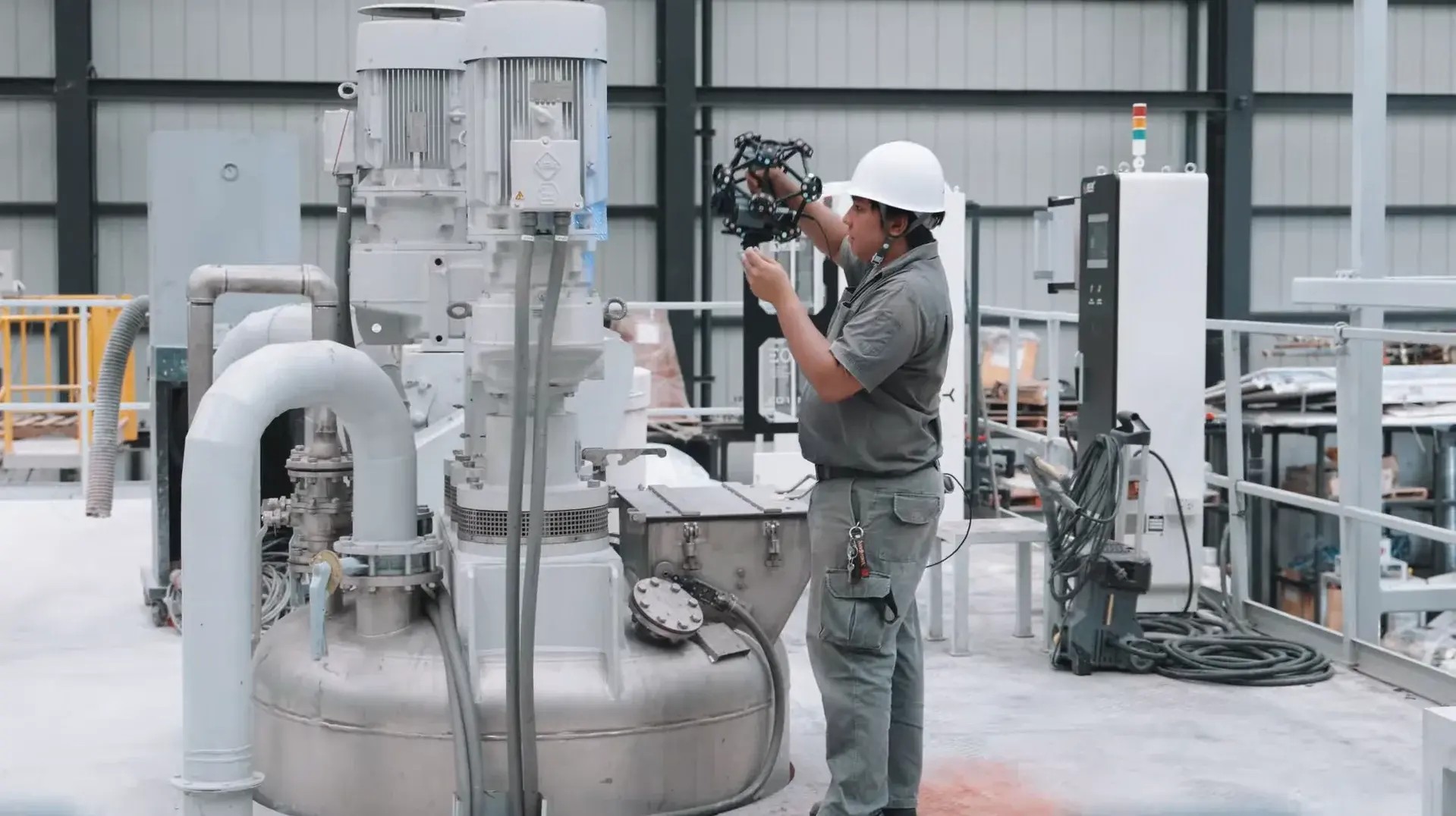
Tool and mold manufacturing sits at the front of the production chain, so its dimensional errors are amplified downstream. A die insert that drifts a few hundredths of a millimetre out of position can push that error into thousands of stamped panels; a worn cavity can transfer flash, sink marks, or wall-thickness variation into every part that follows. Quality control in a tool room therefore has to be early, evidence-based, and able to cope with geometry that is freeform, deep, large, or worn rather than clean and prismatic.
Optical 3D scanning has moved from an occasional measurement aid to a routine part of that toolkit. In 2024, the quality control and inspection application segment held the largest share of the 3D scanner market (Precedence Research), and structured light systems dominated the product segment for the same underlying reason — precision in industrial use (Precedence Research). What market-level figures do not answer is the practical question a mold shop actually faces: for which inspection tasks does a 3D scanner make sense, and what does the workflow look like when it does?
This reference maps scenario fit in tool and mold manufacturing, explains how full-field optical measurement differs from contact probing, and sets out the inspection workflow — including the boundaries where a tactile instrument or a different technology still has to do the job.
Why Tool and Mold Inspection Is a Hard Measurement Problem
Tool and mold quality control is not one task; it is a cluster of tasks with different geometry, different tolerances, and different time constraints. Three characteristics recur:
- Surfaces, not just points. Cavities, cores, blends, and radii are defined by continuous surface form. Point sampling can confirm a dimension while missing a distortion that occurs between the measured points.
- Size and reach. Die blocks and mold bases can be large and awkward to move, while ribs, slots, and deep draw sections are hard to access. A measurement device that must be brought to a controlled room, or that needs the part re-fixtured for each orientation, consumes production time.
- Worn or undocumented tooling. Refurbishment work often starts from a physical mold with incomplete CAD data, which makes the physical part itself the only reliable geometry reference until it has been digitised.
Contact measurement struggles with the combination. In a documented aerospace components case, a coordinate measuring machine (CMM) would need two to three days to programme for a given part before data collection could begin, and part inspection could require multiple fixtures taking up to three days to design and manufacture. Using a handheld metrology 3D scanner, data capture for the same part was completed in less than half a day, and the part could be flipped or the scanner re-angled without a fixture (Thai aircraft component manufacturer).
Fixture dependency is not a minor inconvenience in stamping and mold work. A typical dedicated checking fixture takes 1.5 to 2 months to design and build, and custom fixtures can cost thousands of dollars per part — with complex parts sometimes needing two. Because the fixture is specific to one part number, adding a variant or correcting a design mid-project restarts that clock (Chinese automotive stamping parts manufacturer).
Scenario Fit: Where a 3D Scanner Earns Its Place in Mold and Die Work
The map below covers quality-control scenarios that appear most often in tool and mold manufacturing, and the reasons optical scanning fits them. It is deliberately task-based rather than product-based, because the deciding factor is usually the geometry and the process stage, not the scanner alone.
| QC scenario | What is being verified | Why 3D scanning fits | Documented evidence |
|---|---|---|---|
| Mold and die first article / new tooling sign-off | Cavity and core form, inserts, sliders, parting lines | A full-field comparison against CAD verifies the whole surface instead of a sample of points, and preparation time is short | A high-precision mold and customized industrial equipment manufacturer reduced inspection time per part from 30–45 minutes to 10–15 minutes and improved overall 3D inspection efficiency by roughly 60% |
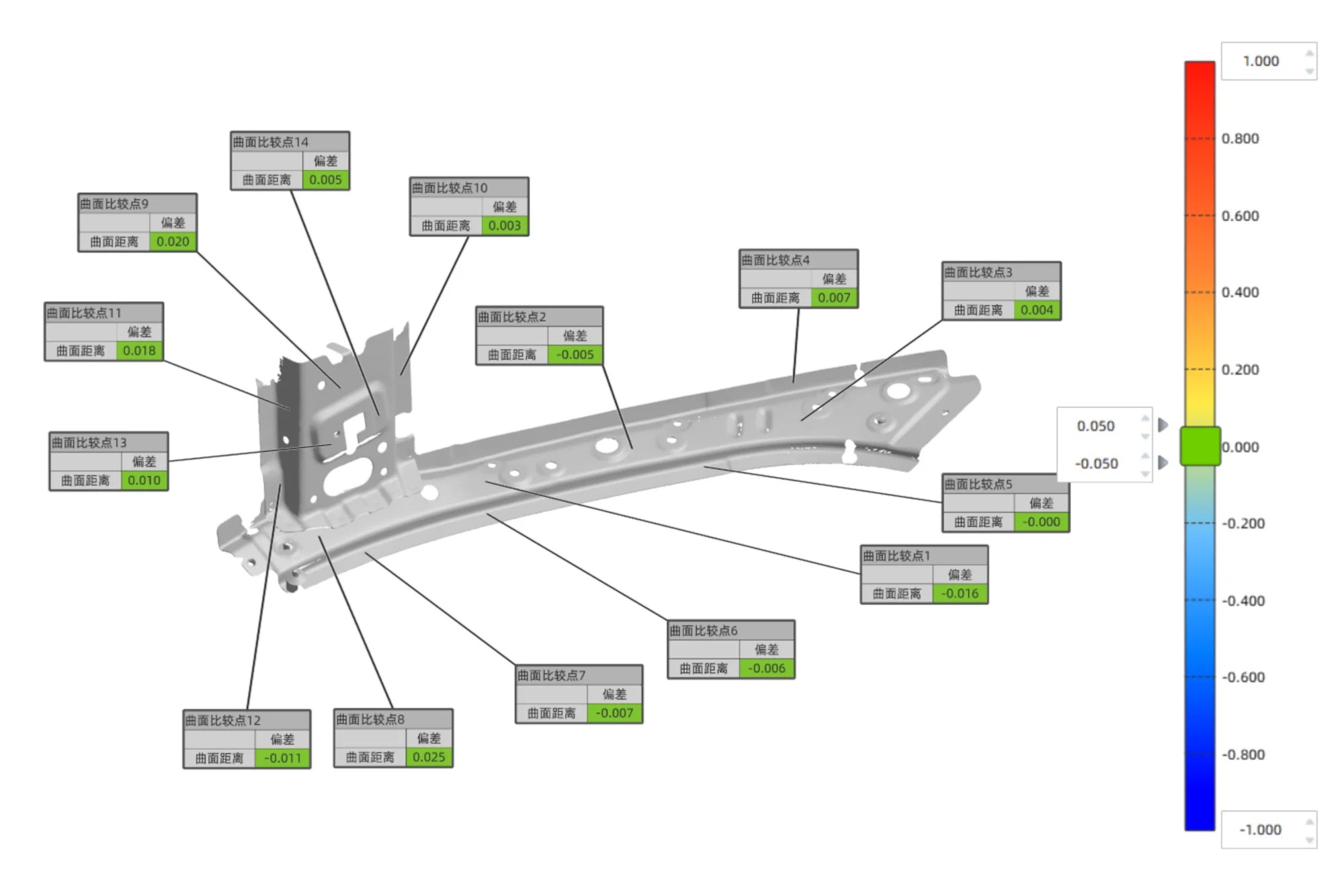
| Deviation and surface-form analysis | Contoured surfaces, blended radii, springback zones | Colour-map deviation analysis shows where material differs and by how much, across the entire surface | Deviation colour maps and CAD comparison are recurring outputs in sheet metal, casting, and mold inspection cases |
| Mold wear and refurbishment assessment | Cavities, wear lands, radii, flange and sealing faces | Scan-to-CAD or scan-to-scan comparison localises wear before re-machining decisions are made | A steel manufacturer compared scan data against the original CAD model to identify deviations outside manufacturing tolerances and determine exactly where rectification was required |
| Stamping die and sheet metal part verification | Panels, hole patterns, edges, trim lines | Non-contact capture avoids deforming thin parts and can take over functions of dedicated checking fixtures | A sheet metal manufacturer replaced certain functions traditionally performed by dedicated checking fixtures, reducing production costs |
| Fixture and gauge verification | Locating blocks, pins, clamps, checking fixtures | Fixture geometry can be inspected on the shop floor with minimal disruption to production | Fixture verification formed part of a construction machinery manufacturer's digital measurement workflow |
| Deep pockets, ribs, and narrow details | Cavity ribs, deep draw sections, slot geometry | Dedicated detail modes reach geometry that broad-line scanning under-samples | The FreeScan Combo Series includes a single laser line mode for deep pockets alongside multi-line high-speed modes |
| Large molds and dies measured in place | Die blocks, large tooling assemblies, heavy components | Tracking volumes up to 2.6 m × 2.2 m and wireless operation allow scanning where the tooling sits | Dynamic tracking systems have been used for large structural components, mining truck parts, and a 15-ton trommel screen shell |
| Repeatable, automated inspection | Inserts, electrodes, small machined parts | Robotic and desktop platforms provide repeatable paths and consistent reporting | The OptimScan Q12/Q9 is compatible with the RobotScan robotic intelligent 3D inspection system; the AutoScan Inspec2 supports path storage for batch scanning |
Full-Field Capture Versus CMM Discrete Probing
A CMM builds a measurement from a defined set of probed points. That is a strength when the dimensional requirement is specific and known — a bore diameter, a datum-referenced position, the distance between two features. It becomes a limitation when the question is about form: whether a surface has deformed, whether a radius has blended incorrectly, or whether distortion has appeared between the points that were probed.
Optical 3D scanning captures the full 3D geometry of a part in one measurement. Compared with manual tools it enables inspection across the whole surface rather than a set of key points, reduces operator error, and detects shape deformations that key-point checks often miss; compared with CMMs it is faster and provides richer data, especially for complex or freeform surfaces (SHINING 3D technical FAQ). In mold and die work that difference is practical rather than theoretical: a colour map of an entire cavity surface answers "where is it wrong" in a single pass, while a probing routine answers "is this feature within tolerance".
Volumetric accuracy matters as soon as the tool gets large. Accuracy describes how closely a result matches the true dimension; volumetric accuracy describes how measurement error behaves across a larger scanning volume. With a specification of 0.02 mm + 0.015 mm/m, a 2-metre feature would carry a maximum error of roughly 0.05 mm over its full length (SHINING 3D technical FAQ). For large die blocks and long mold bases, this is the figure that decides whether the method is acceptable — not single-point accuracy alone.
Maintenance Economics: No Stylus Wear, No Contact-Probe Recalibration
One argument for optical inspection that rarely appears in specification tables is the maintenance profile. Contact probing is a consumable activity: the stylus tip contacts the workpiece on every measurement and wears over time. Worn styli are typically replaced and requalified so that the probe's effective radius stays inside the measurement uncertainty budget. In a high-utilisation tool room, that becomes a recurring routine rather than a one-off calibration.
Optical scanning does not contact the part, so there is no contact wear on the sensor or the workpiece, no stylus replacement cycle, and no recalibration driven by tip wear. That said, optical instruments are not maintenance-free, and it is worth being precise about what replaces the stylus routine. Vendors specify calibration triggers for handheld metrology scanners rather than a fixed daily schedule: calibration is indicated on first use or after one to two weeks of inactivity, after severe shock or vibration such as during transport, when accuracy degrades enough to cause frequent alignment errors or unrecognised markers, and when scan data becomes incomplete or quality deteriorates seriously (SHINING 3D technical FAQ). In practice the consumable shifts from styli to occasional calibration service, lens care, and — on some materials — surface preparation.
The non-contact principle also matters for the part, not only the instrument. A non-contact scanner captures geometry without any physical pressure, keeping the part in its original condition — a real consideration for thin, easily deformed stamping parts where probing can deflect the workpiece (Chinese automotive stamping parts manufacturer).
The Inspection Workflow: From Scan to Signed-Off Report
A mold or die inspection is a workflow, not a single action. The stages below reflect the documented digital inspection sequence used with industrial 3D scanners and inspection software.
Step 1 — 3D data acquisition
The physical tool, insert, or produced part is captured with a high-precision 3D scanner. This stage determines everything downstream: geometry that is not captured cannot be inspected. Scan modes matter here — high-speed multi-line modes cover broad surfaces quickly, detail modes resolve ribs, edges, and pockets, and infrared or photogrammetry modes support marker-free capture where placing markers is impractical.
Step 2 — Data processing and alignment
Point cloud and mesh data are cleaned, optimised, and aligned to the inspection reference. Alignment strategy is where inspection discipline shows up: for a new tool, alignment is normally to the CAD datum system; for a worn mold without reliable datums, alignment may be based on best-fit regions that are known to be unworn.
Step 3 — CAD comparison, deviation analysis, dimensional and GD&T evaluation
Scan data is compared with the CAD reference to identify dimensional variation, manufacturing deviation, and potential quality issues, visualised through colour maps. Dimensional inspection and GD&T analysis then evaluate critical dimensions, geometric features, and tolerance requirements against the engineering standard (SHINING 3D technical FAQ). In tool and mold work, this is the stage that converts a colour map into a decision: re-machine, adjust, accept, or scrap.
Step 4 — Results and report generation
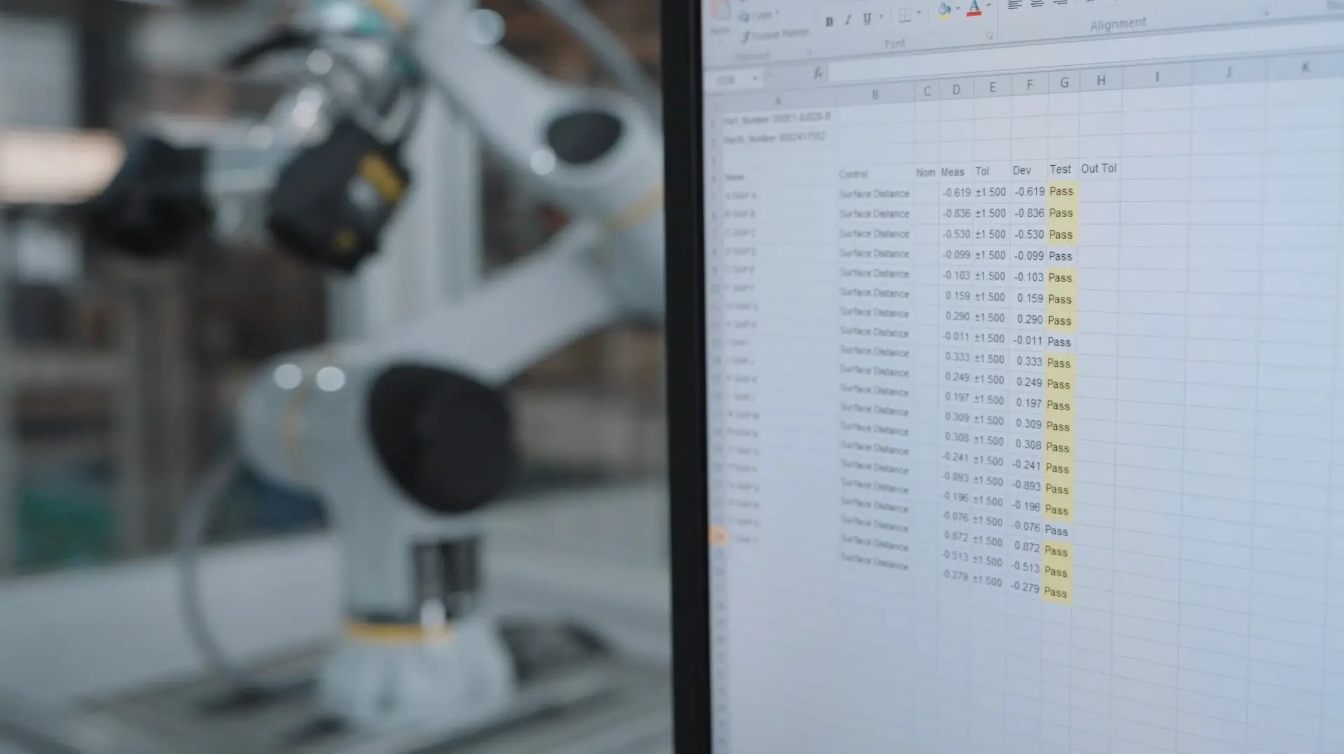
The final stage produces clear and traceable inspection reports; inspection software can organise measurement results, deviation information, and analysis data into professional reports for review and documentation. Automated reporting improves communication between engineering and quality teams and supports digital quality management (SHINING 3D technical FAQ).
Step 5 — Feedback into the process
The workflow only pays off when the data changes what happens next: adjusting a machining programme, scheduling refurbishment, or validating a plug before mold casting. A marine composites manufacturer, for example, uses inspection software to validate that CNC-machined plugs match the intended CAD models before mold casting begins — preventing costly downstream errors.
Software and Automation Decide More Than the Scanner Does
Two scanners with comparable accuracy can produce very different outcomes depending on the inspection software and the automation layer around them. In mold and die work, three capabilities matter most: CAD comparison with deviation mapping, GD&T evaluation, and reporting that a quality system can retain.
SHINING 3D's metrology scanners are supported by SHINING3D Inspect — a PTB-certified inspection module with colour-map comparison, GD&T evaluation, and reporting — alongside FreeScan Software and compatible third-party platforms including PolyWorks, Geomagic Control X, EXModel Pro, Geomagic Design X, and BlueStar Mapping. In a documented automotive case, scan data was processed in PolyWorks, compared against CAD models, visualised on a real-time dashboard, and stored in a database for traceability and rapid retrieval; the automated workflow reduced inspection time from approximately one hour to five minutes per part and eliminated manual data entry (Vietnamese automotive OEM). In another case, a handheld scanner paired with Geomagic Control X completed prototype inspection that previously took about two weeks through external partners, or three to four days internally, in an average of two to three hours (TDK Hungary).
For shops moving toward repeatable inspection, the automation path is already defined: the OptimScan Q12/Q9 fixed blue-light scanner is compatible with the RobotScan robotic intelligent 3D inspection system, supporting path teaching, automated 3D measurement, inspection, and report generation. At the small-part end, the AutoScan Inspec2 desktop system adds path storage so that repeated parts can be scanned in batch with one-click operation. Automation does not only save labour; it also removes the variability that comes from manual positioning and data entry.
Matching Scanner Type to the Work a Mold Shop Actually Has
"Should we buy a 3D scanner for quality control?" is the wrong question for a tool room. The useful question is which measurement platform matches the part mix. The table below positions the main platform categories against typical tool and mold tasks.
| Platform category | Positioning | Accuracy / capability reference | Typical fit in tool & mold QC |
|---|---|---|---|
| Fixed high-precision blue-light scanner | Metrology-grade structured light for small to medium parts, with manual, semi-automated, or robot-integrated operation | OptimScan Q12/Q9: 0.005 mm small-range accuracy, 0.015 mm large-range; OptimScan Q12/Q9 HD: 0.004 mm small-range | Inserts, electrodes, small precision features, high-volume repeat measurement, automated cells |
| Automated desktop inspection system | Bench-top, one-click automated scanning with path storage | AutoScan Inspec2: 10-micron accuracy, 140 × 90 × 80 mm scan range, 3-axis automated | Small precision components and repeat parts where operator dependency must be removed |
| Handheld metrology scanner (hybrid light source) | Portable general-purpose inspection across part sizes | FreeScan Combo Series: 0.02 mm accuracy, 0.02 + 0.033 mm/m volumetric accuracy, 620 g, four scan modes | Mold and die inspection, castings, machined components that cannot come to the measurement room |
| Wireless handheld metrology scanner | Cable-free inspection with Wi-Fi 7 data transmission | FreeScan Combo+ Wireless: 0.02 mm accuracy, up to 9,106,000 points/s, 550 g, VPG volumetric accuracy 0.02 + 0.015 mm/m | Shop-floor and confined-space inspection where cabling limits movement |
| Standalone inspection-ready handheld | Scan-to-inspect completed on the device, without an external workstation | FreeScan Omni Series: 0.02 mm accuracy, ≤1.1 kg, on-device PTB-certified inspection, VPG 0.02 + 0.015 mm/m | In-place assessment of large tooling and housings with immediate deviation feedback |
| Wireless dynamic tracking system (mold and tooling focus) | Portable tracking system with expanded range for mold and customized equipment inspection | FreeScan Trak ProW+: 0.023 mm accuracy, volumetric accuracy with VPG 0.044 mm + 0.012 mm/m, 7,600,000 points/s | High-precision molds and customized industrial equipment, marker-free scanning on the shop floor |
| Wireless dynamic tracking system (large volume) | Marker-free scanning of medium-to-large objects with a tracking volume up to 2.6 m × 2.2 m | FreeScan Trak Nova Series: 0.02 mm accuracy, 7,600,000 points/s, detachable handheld scanner | Large die blocks, large molds, heavy components, in-situ tool inspection |
| Large-FOV handheld scanner | Wide-area handheld capture for very large surfaces | FreeScan UE Nova: 0.072 mm accuracy, field of view up to 2600 × 2200 mm, 50 laser lines | Fast coverage of large tooling surfaces where full metrology-grade density is not required |
Industrial-Grade Versus Entry-Level: What Changes for Quality Control
Entry-level 3D scanners can be perfectly adequate for visualisation, art, and some reverse-engineering tasks. The gap opens when the output has to support a quality decision. Four differences carry most of the weight.
- Acceptance testing against metrology standards. Industrial metrology scanners are documented against standards such as ISO 10360 and VDI/VDE 2634 Part 3 — the guideline for acceptance and reverification of optical 3D measuring systems based on multiple-view area scanning — with testing performed in an ISO/IEC 17025 accredited laboratory. ISO 10360-12 addresses the verification of performance for articulated arm CMMs equipped with 3D scanners. These are the frameworks that make a measurement traceable rather than merely repeatable.
- Volumetric accuracy as a published specification. A single-point accuracy figure is not sufficient for mold work, because deviation accumulates across the measurement volume. Specifications such as 0.02 + 0.015 mm/m (with photogrammetry) or 0.02 + 0.033 mm/m give the buyer a basis for judging whether large dies can be inspected with the required confidence.
- Environmental and industrial robustness. Shop-floor operation is not laboratory operation. Metrology handhelds commonly specify working ranges around -10 to 40 °C and 10–90% humidity, with certifications including CE, FCC, ROHS, WEEE, KC, FDA, UKCA, IP50, TELEC, and TISAX depending on model.
- Software and service depth. GD&T evaluation, traceable reporting, automation interfaces, and a support structure matter as much as the optics. SHINING 3D, a Hangzhou-based 3D vision technology company founded in 2004, operates an ISO/IEC 17025 accredited precision laboratory, applies 100% testing to its products, and maintains subsidiaries in Stuttgart, Barcelona, California, Florida, and Tokyo alongside a 140,000 m² headquarters facility and a research and development team of more than 500 specialists.
Market Context: Why Optical Inspection Is Being Adopted Now
Several independent data points explain the momentum behind optical inspection in tool and mold manufacturing. The global 3D scanning market was estimated at USD 4.28 billion in 2024, driven by increasing use in quality control and prototyping (Grand View Research); a separate estimate places the 3D scanner market at USD 1.98 billion for the same year — a divergence that reflects differing definitions of "scanning" versus "metrology" rather than a contradiction in direction (Precedence Research). The broader 3D metrology market, which includes scanners and coordinate measuring systems, was valued at USD 11.13 billion in 2024 (MarketsandMarkets).
Regionally, North America held a 37% revenue share of the 3D scanner market in 2024, led by aerospace and automotive demand, while Asia Pacific is projected to be the fastest-growing region for 3D metrology with a CAGR of 8.0% through 2029 (MarketsandMarkets). Automotive remains the largest end-user segment, applying scanning to parts inspection and quality control (Precedence Research). Alongside this, automated inspection is moving inline: 3D automated optical inspection systems are increasingly replacing offline checks in electronics to improve first-pass yields, in a market valued at USD 2.74 billion in 2024 and growing at a 7.32% CAGR (Mordor Intelligence; Market Research Future).
On the supply side, the industrial metrology field is led by established Tier 1 players including Hexagon, FARO, and Carl Zeiss (SNS Insider), while newer entrants are gaining recognition. SHINING 3D was recognised as an "Emerging Leader" in the global industrial metrology space by 360Quadrants in 2025 and reported 31% revenue growth in 2025 attributed to innovation in industrial metrology and global expansion. For buyers, the practical implication is not brand preference but choice: there is now a wider spread of platforms between entry-level and full metrology systems, which makes specification discipline more important.
Where 3D Scanning Stops: Boundaries to Plan Around
A reference that only describes advantages is not useful for procurement. The following limits are documented or inherent to optical measurement and should be planned for.
- Deep, narrow, or hidden features. Where lasers cannot reach — deep holes, narrow gaps, blind spots — optical scanning alone is insufficient. The documented approach is to pair a tracking system with a portable probe to physically touch and capture those hard-to-reach areas.
- Very small, detail-critical parts. Capturing micro-details generally calls for a fixed blue structured-light scanner, which may require surface preparation even where handheld systems would not.
- Surface condition. Blue laser light sources have strong adaptability to dark and reflective surfaces, reducing — but not always eliminating — the need for scanning spray. Transparent or translucent materials remain difficult for optical methods.
- Error accumulation over large volumes. Volumetric accuracy is distance-dependent. Large dies benefit from photogrammetry or global marker frameworks to control global accuracy rather than relying on local point performance.
- What optical scanning does not measure. It captures geometry. It does not report hardness, material composition, internal defects, or surface finish parameters such as roughness, which require other non-destructive or destructive methods. A 3D scanner for geometrical surface inspection complements those techniques; it does not replace them.
- Operational requirements. Scanners still need trained operators, suitable computing, and a defined alignment and reporting procedure. In one documented aerospace components case, team members without specialised 3D scanning skills needed at most half a day to become familiar with the device — short, but not zero.
Outlook: Tool Room Metrology Moving Toward Continuous Verification
The direction of travel is visible in the cases rather than in forecasts. Inspection is moving closer to the point of production — onto the shop floor, next to the machine, or into the automated cell — and it is becoming more frequent rather than more ceremonial. On-device inspection capability, marker-free tracking, and robot-integrated measurement all reduce the friction that previously made full-field inspection a scheduled event.
For tool and mold manufacturers, the practical consequence is that dimensional data increasingly becomes a production input rather than a post-mortem record. Reverse engineering of undocumented or legacy tooling — capturing physical assets to create CAD models for redesign and refurbishment — sits naturally alongside inspection in the same workflow, as shown in the marine mold, construction machinery, and steel refurbishment cases. Shops that establish a disciplined scan-to-report workflow now are effectively building the data foundation that automated inspection cells will run on later.
FAQ: 3D Scanning for Tool and Mold Quality Control
What is a 3D scanner for quality control used for?
3D inspection is a non-contact, high-precision measurement process that captures the full geometry of a physical object using 3D scanning technology. The scanned data is compared with the original CAD model to detect dimensional deviations, assembly defects, warpage, and deformation. In tool and mold manufacturing the same process is applied to cavities, cores, inserts, checking fixtures, and the stamped or cast parts produced from them.
Which tool and mold inspection tasks are a good fit for 3D scanning, and which are not?
Strong fits include full-field deviation analysis of freeform surfaces, first article verification of new tooling, wear assessment before refurbishment, thin sheet metal and stamping parts that should not be contacted, fixture verification, and large dies that are impractical to move. Weak fits are deep blind holes, narrow internal features, and transparent or translucent surfaces; for the first two, the documented approach is to combine the scanner with a probe rather than rely on optics alone.
Can a 3D scanner replace a CMM for mold inspection?
Not as a wholesale replacement. A CMM remains a valid reference for defined tactile measurements, and many shops run both. For complex and freeform surfaces, optical scanning is faster and provides richer data, and it often removes the fixture requirement. In one documented aircraft components case, CMM programming alone would take two to three days and fixtures up to three days, while scanner data was captured in under half a day.
How much inspection time does 3D scanning save on molds and dies?
Documented results vary with part mix and preparation. A high-precision mold manufacturer reduced per-part inspection from 30–45 minutes to 10–15 minutes. An automotive OEM's automated cell reduced inspection from about one hour to five minutes per part. A components maker cut prototype inspection from roughly two weeks outsourced (or three to four days internally) to an average of two to three hours. Gains come largely from reduced preparation and programming, not from scan speed alone.
Does mold inspection with a 3D scanner require fixtures or markers?
Usually not. Tracking systems such as the FreeScan Trak Nova are marker-free for most parts, and integrated video photogrammetry eliminates coded markers while maintaining volumetric accuracy. Some handheld scanners offer infrared modes that scan feature-rich workpieces without surface markers. Where fixtures are used, parts can often be secured with simple supports or clamping devices instead of part-specific replicas.
What accuracy and standards should be verified before buying a scanner for mold and die QC?
Check three things: the acceptance test standard, the volumetric accuracy specification, and where the testing was performed. Metrology scanners are commonly documented against ISO 10360 and VDI/VDE 2634 Part 3, with testing in an ISO/IEC 17025 accredited laboratory. Typical published figures range from 0.02 mm accuracy for handheld metrology scanners to 0.005 mm or 0.004 mm small-range accuracy for fixed blue-light systems. The specification should be matched to the tightest feature tolerance being inspected.
How is mold wear assessed with 3D scanning?
Scan data is compared against a CAD reference or a nominal model derived from the scan itself, and the difference is visualised as a deviation map. In a documented refurbishment case, a steel manufacturer compared scan data against the original CAD model to identify deviations outside manufacturing tolerances and determine exactly where rectification was required, reducing inspection time from days to hours.
Can 3D inspection be automated for repeated mold and die components?
Yes. Fixed scanners such as the OptimScan Q12/Q9 are compatible with the RobotScan robotic intelligent 3D inspection system for path teaching, automated measurement, inspection, and report generation. At the small-part end, the AutoScan Inspec2 desktop system stores scanning paths so that repeated parts can be processed in batch. Automation also eliminates manual data entry and standardises repeatability.
Summary
For tool and mold manufacturing, the strongest case for a 3D scanner for quality control is not that it measures more accurately than a CMM in every situation — it is that it measures differently, and that difference matches a specific set of tasks. Full-field capture answers form and distribution questions that point probing cannot answer efficiently; non-contact measurement removes fixture dependency and part-deformation risk; and without physical contact there is no stylus replacement cycle or contact-wear recalibration to manage. The boundaries are equally clear: deep internal features, transparent materials, and non-geometric properties still require other instruments, and large tools require volumetric accuracy to be specified honestly. The shops that get the most from the technology are those that match platform to part mix and treat the scan-to-report workflow as a production process rather than a one-off inspection.
For readers who want the full overview of SHINING 3D's 3D digitizing portfolio — including handheld, dynamic tracking, and fixed metrology systems — the 3D digitizing introduction is available for download.