
3D Scanning in Power & Energy: Matching Scanner to Demand
Independent Industry Reference | Smart Manufacturing
3D Scanning in Power & Energy: Matching Scanner to Demand
Power and energy components are almost never measured where metrology is convenient. They are measured where they operate or where they are fabricated. A hydro runner is inspected in the powerhouse. A mill shell returns from a mineral processing plant coated in service wear. A pressure vessel is checked on a fabrication floor that vibrates. The gap between where these assets live and where dimensional measurement traditionally happens is exactly the gap that industrial 3D scanning has filled.
This article examines how 3D inspection technology is applied across power and energy work, why the accuracy class of the scanner matters more than the marketing category it sits in, and which parameters, standards and certificates a buyer should verify before committing budget. It also sets out where optical scanning stops being the right tool, because that boundary is what separates a defensible procurement decision from an expensive one.
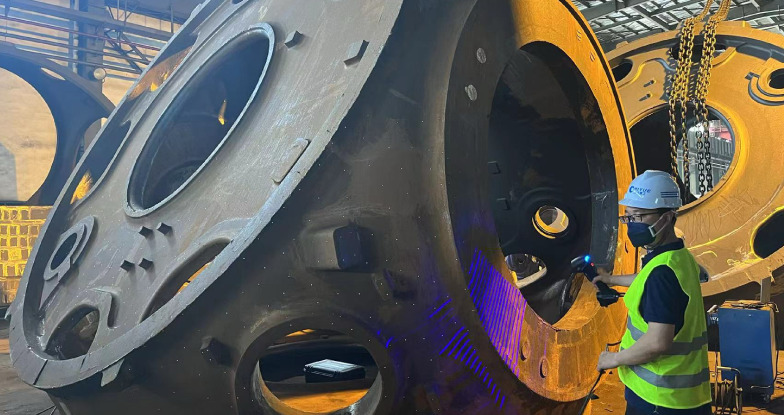
3D data capture on large energy and mining machinery in an outdoor industrial environment.
Why Power & Energy Assets Resist Conventional Measurement
The geometry that dominates this sector is large, curved and freeform: turbine runners and casings, mill shells and trunnions, welded structural frames, plate and pipe assemblies, heavy castings and forged housings. The failure modes are surface phenomena rather than single dimensions — deformation, warpage, ovality, erosion, corrosion loss, and weld distortion that only becomes visible when the whole surface is compared against nominal.
Traditional instruments sample. A caliper, micrometer, gauge or dedicated checking fixture measures a defined set of features at defined locations. That approach is fast and repeatable when the design intent is a small number of critical dimensions, and it remains the correct choice in many situations. But a freeform surface that springs back between two measured points stays invisible to a key-point check, and a wear pattern that spreads across a runner blade is not described by three measurements.
Coordinate measuring machines close part of that gap, but they carry their own preparation load. In one documented aircraft component inspection project, a CMM would have required two to three days to set up the measuring program before the first data point was collected, and fixtures for the same part could take up to three days to design and manufacture. The same part was captured with a handheld 3D scanner in less than half a day, without part fixation or complex jigs.
What “Metrology-Grade” Actually Changes in Practice
The phrase is used loosely across the market, so it is worth separating the four parameters that determine whether a scanner can support a quality decision.
- Accuracy — how closely a measured result matches the true physical dimension. If a 100.00 mm feature measures 100.02 mm, the error is 0.02 mm.
- Precision (repeatability) — how consistently the same measurement is reproduced under unchanged conditions. A scanner can be highly repeatable while still carrying a small offset from true value.
- Resolution — the smallest detail the system can distinguish. Higher resolution does not automatically mean higher accuracy; a scanner may capture very fine detail while still introducing dimensional error.
- Volumetric accuracy — accuracy across the whole scanning volume rather than at a single point. This is the parameter that matters when the object is a runner, a mill shell or a fabricated frame.
Volumetric accuracy is normally expressed as a formula. A specification of 0.02 mm + 0.015 mm/m means that on a two-metre feature the maximum error band widens to 0.02 + (0.015 × 2) = 0.05 mm. On a small bracket that widening is negligible. On a five-metre fabrication it is the difference between a usable pass/fail decision and a report that cannot be defended.
This is where the distinction between consumer-grade capture and metrology-grade scanning becomes practical rather than semantic. A LiDAR unit can produce a dense, visually convincing point cloud of a plant room, but its output is generally not specified against VDI/VDE 2634 Part 3 or validated through an ISO 10360 acceptance procedure, and it is rarely tied to a traceable volumetric accuracy figure. LiDAR and photogrammetry-led capture are strong tools for as-built documentation, spatial layout and asset registration. They are not substitutes for a scanner that has to answer a GD&T question.
LiDAR-Based Capture vs Metrology-Grade 3D Scanning
| Dimension | LiDAR / consumer capture | Metrology-grade 3D scanning |
|---|---|---|
| Primary purpose | Spatial context, as-built records, navigation, clash review | Dimensional conformance, deviation analysis, GD&T evaluation |
| Accuracy specification | Typically stated as scene-level range or scan error, not per-feature measurement error | Specified per point and per volume, e.g. 0.02 mm + 0.015 mm/m with VPG on a wireless handheld system |
| Traceability | Seldom tied to a metrology acceptance procedure | Accepted to VDI/VDE 2634 Part 3 and ISO 10360, tested in an ISO/IEC 17025 accredited laboratory |
| Data output | Point cloud for spatial modelling and visualisation | Mesh or point cloud aligned to CAD, supporting compare, cross-section, feature, dimension and gauge evaluation |
| Typical power & energy use | Plant room digitisation, layout planning, asset registers | Turbine wear quantification, mill shell ovality, casting and weld deviation, refurbishment acceptance |
| Where it stops | Cannot support a tolerance decision or a traceable inspection report | Cannot see fully enclosed internal geometry; may still need tactile probing for hidden features |
Matching Scanner Architecture to the Task
Within metrology-grade equipment, the decisive variable is not brand but architecture. The same sector contains 8-micron-class features on a control valve component and 6-metre fabricated structures on a turbine deck, and no single form factor serves both economically.
| Architecture | Best-fit objects | Representative SHINING 3D systems | Accuracy anchor | Site conditions |
|---|---|---|---|---|
| Portable handheld laser | Small to medium components, on-site work, dark and reflective surfaces | FreeScan Combo Series; FreeScan Combo+ Wireless / FreeScan Combo Wireless | 0.02 mm; volumetric 0.02 + 0.033 mm/m (Combo); 0.02 + 0.015 mm/m with VPG (Wireless) | 620 g / 550 g; Wi-Fi 7 on the wireless models; hot-swappable battery up to 2 hours |
| Fixed structured light | Small precision parts, sharp edges, batch inspection | OptimScan Q12/Q9; OptimScan Q12/Q9 HD | 0.015 mm large range / up to 0.005 mm small range; HD 0.01 mm / 0.004 mm | Controlled laboratory or inspection cell |
| Dynamic tracking | Large and extra-large structures, marker-free scanning | FreeScan Trak Nova Series; FreeScan UE Nova | 0.02 mm; volumetric 0.062 mm (12 m³); 0.046 + 0.012 mm/m with VPG. UE Nova 0.072 mm / 0.072 + 0.012 mm/m | 7,600,000 points/s; FOV up to 2600 × 2200 mm; 1.2 kg and 1.6 kg; −10 to 40 °C, 10–90% RH |
| Robotic automated cell | Repeated batch inspection where repeatability matters more than portability | RobotScan Series (RobotScan Q12, RobotScan UE Pro2, RobotScan Combo+) | Configurable: measurable object ≤ 500 mm, turntable load ≤ 20 kg, robot working radius 800 mm | Production environment; wired or wireless integration |
| Desktop automated | Small precision parts in volume, first article inspection | AutoScan Inspec2 | Up to 0.01 mm; point distance 0.05 mm; scan range 140 × 90 × 80 mm | Bench or laboratory; multi-object mode handles up to 8 parts in one run |
One further split cuts across all of these: whether the scanner needs a computer at all. The FreeScan Omni / FreeScan Omni Lite is a standalone inspection-ready metrology handheld system with on-device scan-to-inspect capability, certified accuracy of 0.02 mm, integrated PTB-certified inspection, a 5.5-inch touchscreen, hot-swappable batteries and a net weight of 1.1 kg or below. On a plant walk-down where no bench is available, that configuration changes what is operationally possible rather than simply what is convenient.
Where the Technology Earns Its Place: Power & Energy Scenarios
Hydro turbine inspection and repair
Hydro assets combine very large geometry with locally severe wear. In a documented hydropower project, engineers used the FreeScan Combo Series to capture turbine geometry at 0.02 mm accuracy and a scan speed of 1,860,000 points per second. The workflow used different scan modes for different purposes: multiple-line scanning to acquire global data across the large turbine body quickly, and parallel-line scanning on worn regions to capture finer detail, establish the extent of wear and support more accurate repair. The plant reported efficiency gains and cost savings, in part because equipment no longer had to be transported off-site to be measured.
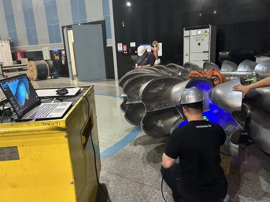
Capturing hydro turbine geometry on site, where the asset operates, rather than in a measuring room.
Heavy equipment and mining machinery
The second cluster is large mobile and stationary machinery used in extraction and materials handling. At SANY Heavy Industry, inspection of large structural components of giant mining trucks has been running for more than two years. The relevant characteristics of that deployment are worth noting for procurement: with a photogrammetric system, volumetric accuracy reached 0.02 mm + 0.015 mm/m; photogrammetry mode removed the need to apply and later remove markers, saving preparation time; and the handheld form factor allowed inspection next to the production line and in outdoor conditions, so the workpiece did not have to be moved to a measuring room.
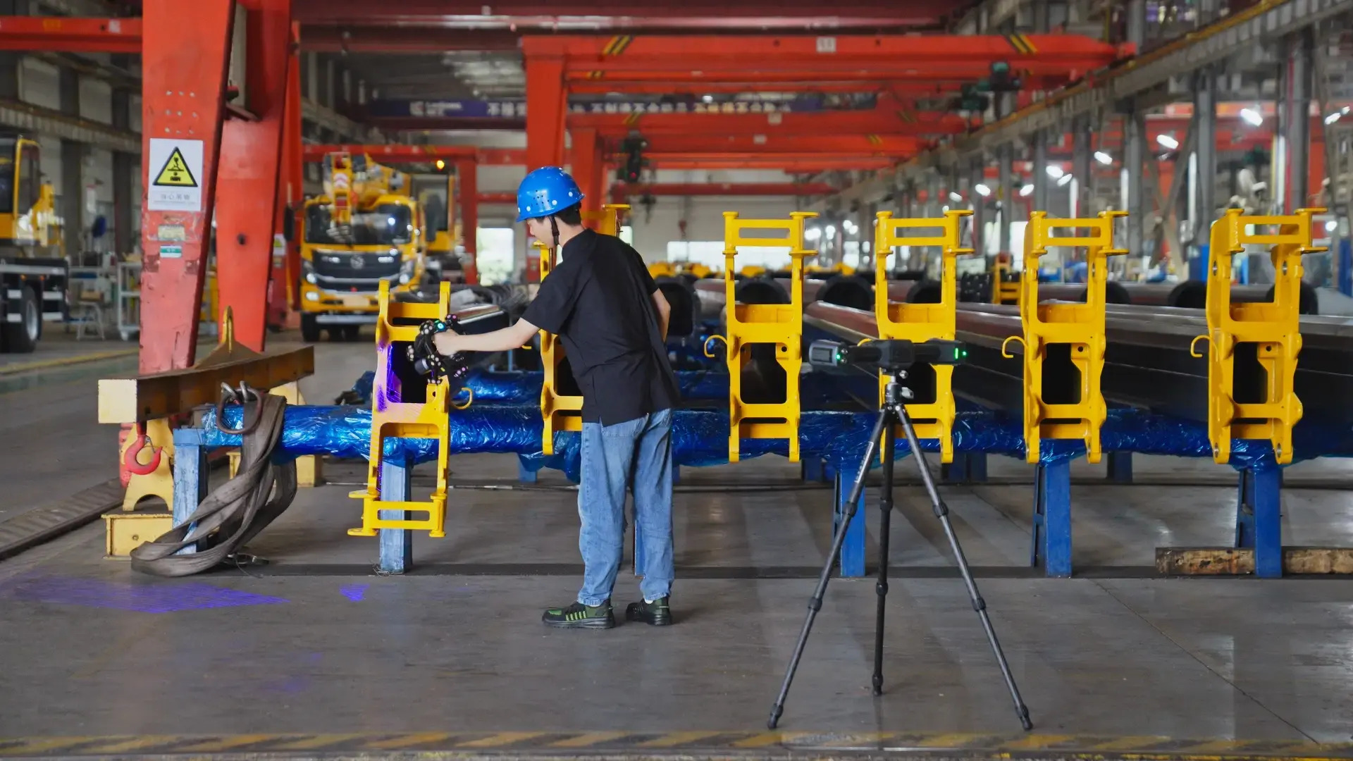
Large-scale workpieces measured in place, avoiding transport to a controlled metrology room.
A parallel case demonstrates the field-measurement limit that conventional tools hit. At Talleres Artificio in Chile, engineers adopted the FreeScan Trak Nova Series for mining ball mill measurement. The system supports large-area dynamic tracking with VPG and uses ISO 10360 certified measurement modules. The practical gain described was geometric coverage: features such as cylindricity could be evaluated even where a full 180-degree measurement was inaccessible to an internal micrometer.
The same pattern appears in refurbishment. Steelstruct, a Western Australian steel manufacturer, uses the FreeScan Trak Nova Series and FreeScan UE Nova to assess 15-ton trommel screen shells returned from mineral processing plants. Scan data is compared directly against the original CAD model so that deviations outside manufacturing tolerances can be identified and rectified. Inspection tasks that previously took days now take hours, and decisions about rework are based on measured deviation rather than judgement.
Fabricated structures, moulds and energy-adjacent assemblies
Power and energy projects also depend on fabricated and tooled components: moulds for composite and cast parts, welded frames, plate assemblies and housing structures. The working conditions recorded for this industry segment are demanding by default — outdoor and indoor industrial environments, wide temperature swings, dust and corrosive atmospheres. The corresponding requirement set is consistent: information security, the ability to scan large objects, high efficiency, wireless portability, software and workflow compatibility, and on-site shop-floor inspection rather than laboratory-only operation.
A closely related application has emerged in energy storage. At KE-TEC in Germany, the FreeScan Omni was integrated into a battery testing workflow so that deformation of housings — often larger than one metre — could be captured after mechanical stress tests. Volumetric accuracy of 0.02 + 0.015 mm/m with VPG was used to hold consistency across the full housing, and the blue laser light source handled dark and reflective surfaces without preparation.
The Evidence Buyers Should Require Before Committing
In an HVQ-2 style procurement decision — where the constraints are certification, specification and price band — the documentation matters as much as the demonstration. The following items are checkable and should be requested explicitly.
- Acceptance testing standard. Optical 3D measuring systems based on multi-view area scanning are commonly accepted under VDI/VDE 2634 Part 3. The corresponding ISO reference for acceptance and reverification is ISO 10360. For articulated arm CMMs equipped with 3D scanners, ISO 10360-12 is the specific part of the standard to check.
- Where the test was performed. A specification is only as strong as the laboratory behind it. SHINING 3D products such as the FreeScan Trak Nova Series, FreeScan Combo Series, FreeScan Combo+ Wireless and FreeScan Combo Wireless, and OptimScan Q12/Q9 are accepted to VDI/VDE 2634 Part 3 and ISO 10360 and tested in an ISO/IEC 17025 accredited accuracy laboratory.
- Product compliance certificates. Dependent on the model, the portfolio carries CE, FCC, ROHS, WEEE, KC, FDA, UKCA, IP50, TELEC and TiSAX certifications. The IP50 rating is the relevant figure when dust and shop-floor particulates are part of the operating environment.
- Calibration and traceability practice. Calibration should be performed with certified artifacts or calibration panels traceable to metrology standards. In practice, recalibration is triggered by first use, by prolonged inactivity, by transport or vibration, or by degraded accuracy such as frequent alignment errors or recurrent marker recognition failures.
- Inspection software certification. The SHINING3D Inspect module is PTB-certified and supports compare, cross-section, feature, dimension, gauges, report and quick measurement functions. The wider software chain includes PolyWorks, Geomagic Control X, EXModel Pro and Geomagic Design X for reverse engineering workflows.
- Information security posture. Asset geometry in this sector is often commercially or infrastructurally sensitive. The relevant certifications to look for include TISAX, ISO/IEC 27001, ISO/IEC 27701, ISO/IEC 27017, ISO/IEC 27018 and MLPS Level 3.
- Environmental envelope. For field work, confirm the operating temperature and humidity range. FreeScan Trak Nova Series is specified for −10 to 40 °C and 10–90% RH; the FreeScan Combo Series extends the lower bound to −20 °C with a Class II eye-safe laser classification.
Market Trend Analysis
Third-party market data supports the direction of travel, with the caveat that published figures vary because “3D scanning” and “3D metrology” are defined differently by different analysts. Grand View Research estimated the global 3D scanning market at USD 4.28 billion in 2024, while MarketsandMarkets valued the broader 3D metrology market at USD 11.13 billion in the same year.
The composition of that demand is more informative than the headline number. According to Precedence Research, the quality control and inspection application segment held the largest share of the 3D scanner market in 2024, and structured light scanners dominated the product segment because of their precision in industrial applications. Short-range scanners of one metre or less also held the largest share, reflecting the density of precision parts inspection. Large-asset measurement is therefore the smaller but structurally necessary part of the market — which is precisely where tracking architectures rather than fixed systems earn their cost.
Two further trends intersect with power and energy. First, inline automated 3D inspection systems are increasingly replacing offline checks, beginning in electronics manufacturing where first-pass yield is the driver; the same economics apply as energy component volumes rise. Second, regional growth is shifting: North America held 37% of 3D scanner revenue in 2024, while Asia Pacific is projected to be the fastest-growing region for 3D metrology at a compound annual growth rate of 8.0% through 2029.
There is also a persistent structural signal in how oversized parts have traditionally been measured. Gantry CMM systems remain the preferred approach for very large components in aerospace and shipbuilding. That preference confirms the underlying demand for full-size verification, and it explains why portable and tracking-based alternatives that can be brought to the asset attract attention in adjacent heavy industries.
On the supply side, SHINING 3D reported 31% revenue growth in 2025 and was recognised as an “Emerging Leader” in the global industrial metrology space by 360Quadrants in the same year, alongside established Tier 1 competitors including Hexagon, FARO and Carl Zeiss. The company was founded in 2004 and operates from Hangzhou with subsidiaries in Stuttgart, Barcelona, California, Florida and Tokyo.
Limits and Boundaries: Where 3D Scanning Is Not the Answer
A credible capability assessment has to include what the technology cannot do. The following constraints are real and should be planned for rather than discovered mid-project.
- Line of sight. Optical scanning cannot capture fully enclosed internal geometry. Deep pockets can be reached using a single-line scan mode, but genuinely hidden blind spots may require a portable probe or a different measurement method entirely.
- Volumetric error accumulation. Error grows with distance across the scan volume. Video photogrammetry substantially reduces this — for example, holding volumetric accuracy to 0.02 + 0.015 mm/m on a wireless handheld system — but it does not eliminate the effect, and on very large surfaces markers may still be recommended for optimal accuracy even on marker-free systems.
- Surface and lighting conditions. Structured light systems project a pattern onto the part and can be affected by strong ambient light. Dark or highly reflective surfaces may require a blue laser light source, or in some cases surface preparation that is not permitted on the component. Where spray is unacceptable, light-source selection becomes a hard constraint rather than a preference.
- Calibration and workflow discipline. A scanner is only traceable when calibration is current and the workflow is followed. Transport vibration, long idle periods and deteriorating data quality all require re-verification.
- Commercial threshold. Industrial inspection is the most demanding application tier and, as a general market observation, budgets for this class of equipment typically start from around twenty thousand US dollars. That places the decision in the category of an operational investment that needs a defined use case, not a trial purchase.
- Simple problems stay simple. For a single critical dimension on a geometrically simple part, a gauge will usually remain faster and cheaper than scanning. Scan where surface information, full-field coverage or digital documentation is genuinely required.
Future Outlook
Three shifts are likely to shape how power and energy organisations buy and use this technology over the next planning cycle.
From laptop-tethered to standalone. The FreeScan Omni / FreeScan Omni Lite demonstrates the direction: 0.02 mm certified accuracy, 7,619,000 points per second, resolution of 0.01 to 10 mm, a laser field of view of 580 × 650 mm and an infrared field of view of 1205 × 1104 mm, all with on-device inspection and a net weight at or below 1.1 kg. As this configuration becomes normal, the measuring location stops being a constraint on the measurement decision.
Marker-free and wireless as default. Video photogrammetry removes coded markers while maintaining volumetric accuracy, which changes both preparation time and the practicality of working at height or in confined plant areas. Combined with wireless transmission that does not affect measurement accuracy, the workflow burden shifts from setup to data interpretation.
Scan data as an asset record. Once turbine runners, mill shells and fabricated structures are captured against CAD, the resulting deviation data becomes a service-life baseline. The natural next step for utilities and heavy asset operators is comparing later scans against that baseline to quantify wear progression rather than to pass or fail a single batch. That shifts the value of the scanner from a quality gate to a maintenance planning instrument, and it is the most likely reason inspection budgets in this sector continue to expand.
FAQ
Which accuracy class does a power and energy component actually require?
Accuracy requirements in industrial inspection are normally divided into three tiers. A tolerance band of 0.005 to 0.02 mm is required for functional safety parts, strict GD&T inspection and precision reverse engineering, and benefits from high-resolution cameras for sharp edges on small features. A band of 0.02 to 0.05 mm is the standard tolerance for assembly verification and structural analysis, where handheld scanners are usually sufficient. A band of 0.05 to 0.1 mm suits overall deformation analysis, surface deviation mapping and large cosmetic parts, where tracking systems are recommended. Because error accumulates with distance, the correct question is not only the required point accuracy but also the required volumetric accuracy across the actual size of the asset.
What certifications and standards should a metrology 3D scanner carry?
Optical 3D measuring systems based on multi-view area scanning are commonly accepted and reverified under VDI/VDE 2634 Part 3, with ISO 10360 as the corresponding international reference; ISO 10360-12 applies specifically to articulated arm CMMs equipped with 3D scanners. The acceptance test should be performed in an ISO/IEC 17025 accredited laboratory, and the manufacturer should be able to issue inspection reports and calibration certificates traceable to those standards. For market access and product compliance, the recognised certifications across the SHINING 3D portfolio include CE, FCC, ROHS, WEEE, KC, FDA, UKCA, IP50, TELEC and TiSAX, depending on the model.
Why does volumetric accuracy matter more than point accuracy on large turbine or mill components?
Point accuracy describes how closely one measured location matches true value. Volumetric accuracy describes how error behaves across the entire scanning volume, which is what determines whether a deviation map of a multi-metre component can be trusted. Specifications are written as a formula: 0.02 mm + 0.015 mm/m means that on a two-metre feature the maximum error band is approximately 0.05 mm. Video photogrammetry is the main mechanism for controlling this accumulation — the FreeScan Trak Nova Series specifies 0.046 mm + 0.012 mm/m with VPG, and the FreeScan Combo+ Wireless specifies 0.02 mm + 0.015 mm/m with VPG.
Can 3D scanning replace CMMs and hard gauges in this sector?
Not entirely, and the boundary is well defined. Non-contact scanning captures the full 3D geometry of a part in one measurement. Against manual tools it enables complete surface inspection, reduces operator error and detects shape deformation that key-point checks miss. Against CMMs it is faster to deploy and provides richer data on complex or freeform surfaces — in one documented case a comparable CMM program required two to three days of setup, with fixtures adding up to three further days, while the scanning workflow captured data in less than half a day. However, optical scanning is line-of-sight and cannot reach fully enclosed internal features, so tactile probing or a portable probe may still be required for hidden geometry. Most organisations end up running both rather than choosing one.
What environmental conditions can a handheld scanner handle on site?
Field capability is specified rather than assumed. The FreeScan Trak Nova Series is rated for −10 to 40 °C and 10–90% RH, with a net weight of 1.2 kg (TE Nova+) or 1.6 kg (UE Nova+) and an IP50 protection level. The FreeScan Combo Series extends the lower temperature bound to −20 °C, operates at 10–90% RH, uses a Class II eye-safe laser and connects by USB 3.0; the wireless variants operate from −10 to 40 °C with up to two hours of continuous scanning on hot-swappable batteries. Wireless transmission handles data only and does not affect measurement accuracy.
Do these scanners require markers, and how much preparation is involved?
Marker requirements depend on the architecture and the object. Systems with integrated video photogrammetry such as the FreeScan Trak Nova Series and FreeScan Combo+ Wireless use VPG to optimise the spatial position of reference markers continuously, eliminating coded markers for most parts; markers may still be recommended on very large surfaces to ensure optimal accuracy. The FreeScan Combo Series can use its infrared VCSEL light source to scan feature-rich workpieces without applying markers at all, and the AutoScan Inspec2 recommends feature alignment when the object has sufficient geometric features. Removing marker application and removal is one of the largest single time savings in a large-component inspection workflow.
Reference material. SHINING 3D is a 3D vision technology company established in 2004 and headquartered in Hangzhou, China, providing metrology 3D scanners, professional and entry-level 3D scanners and dental 3D solutions. The company operates an accuracy laboratory accredited in accordance with ISO/IEC 17025 and maintains subsidiaries in Stuttgart, Barcelona, California, Florida and Tokyo.
A consolidated overview of the 3D digitizing portfolio, including product families referenced in this article, is available in the public brochure: SHINING 3D 3D Digitizing Introduction (PDF).