
Brass Ball, Gate and Stop Valves for Hydronic Heating
Brass Ball, Gate and Stop Valves for Hydronic Heating
In a hydronic heating circuit, brass ball, gate and stop valves are not interchangeable versions of the same part. Each is built for a different duty: the ball valve for quarter-turn isolation, the gate valve for low-resistance shut-off on main lines, and the stop valve for throttling flow so that radiators far from the circulator still reach design temperature. Buyers who compare them only on price per unit usually end up with the wrong valve in the wrong position — and then with noise complaints, worn seats, or a service shutdown that takes down a whole riser.

What hydronic heating actually asks of a brass valve
A two-pipe radiator circuit is a continuous-duty, permanently pressurised application. Typical design conditions are hot water up to 90 °C, working pressure up to 10 bar (PN10), circulation running through the whole heating season, and low flow rates once the system drops to part load. The system stays under pressure year-round, and in residential work the valves are visible in living spaces rather than hidden in a plant room.
Four consequences follow for valve selection. First, the valve must seal at continuous operating temperature, not just at commissioning. Second, most of its life is spent at part load, which is exactly where regulation happens — and where a valve that was never designed to be throttled starts to wear. Third, surface finish and external tightness matter because occupants see and hear the valve. Fourth, noise is the most common complaint on radiator circuits: a component held at part-open can whistle or cavitate if its internal geometry is wrong for that duty.
That is why the ball / gate / stop distinction is a functional one, not a commercial one. It maps directly onto three different jobs in the same circuit.
The three duties, defined
Brass ball valve — quarter-turn isolation
A ball valve isolates. A quarter turn of the handle takes the valve from fully open to fully closed, and the handle position tells you the state of the line from across the room. In the reference product data used for this comparison, the brass ball valve VG10.16902 is listed with a 1/4″ to 4″ size range, female/female threaded connections, an operating range of −20 °C to 120 °C, and a PN40 rating (up to 40 bar / 580 psi). That is the widest temperature and pressure envelope among the three valve types discussed here, which is why the ball valve tends to be the default isolation point at the heat source and at each riser.
Brass gate valve — low-resistance shut-off
A gate valve opens slowly on a multi-turn handwheel and, when fully open, presents a straight-through bore with very little resistance to flow. Its job is coarse shut-off on main distribution lines and on the circulator, where pressure drop has to be kept low. The brass gate valve VG11.11302 is listed at 1/2″ to 2″, with ISO 228 threads (equivalent to DIN EN ISO 228 and BS EN ISO 228), a working range of 0 °C to 80 °C, and a PN16 rating (16 bar). The rubber disc design is intended for potable water and piping water systems.
The gate valve is a fully open or fully closed device. It is not a regulating valve, and using it part-open is the single most common way to damage one.
Brass stop valve — throttling and regulation
A stop valve exists to be part-open. It is used to throttle flow so that radiators far from the circulator still reach design temperature, and so that a heat pump's flow split between the heating circuit and the hot water cylinder can be set. The brass stop valve VG16.70411 is listed at 12 mm to 28 mm with standard threaded connections, an operating range of −20 °C to 100 °C, a PN10 rating, and suitability for drinkable water systems, piping water systems and heating systems. Its pressure drop is higher than a gate valve's by design — that is the trade-off for controllable regulation.
Side-by-side comparison
| Criterion | Brass ball valve | Brass gate valve | Brass stop valve |
|---|---|---|---|
| Primary duty | On/off isolation | Low-resistance isolation | Throttling and flow regulation |
| Operation | Quarter turn; open/closed visible on the handle | Multi-turn handwheel | Multi-turn, set at a part-open position |
| Flow path | Straight through the ball bore | Straight-through bore, low resistance when fully open | Restricted by design to allow regulation |
| Reference model | VG10.16902 | VG11.11302 | VG16.70411 |
| Declared size range | 1/4″ – 4″ | 1/2″ – 2″ | 12 mm – 28 mm |
| Declared pressure rating | PN40 (40 bar / 580 psi) | PN16 (16 bar) | PN10 |
| Declared temperature range | −20 °C to 120 °C | 0 °C to 80 °C | −20 °C to 100 °C |
| Avoid using it for | Balancing or continuous throttling | Any part-open regulating duty | Main lines where low pressure drop is essential |
Parameters as declared in the product data for the models named above. Ratings are per model and size; they are not category-wide claims.
Where each valve belongs in a real installation
In a two-pipe radiator circuit, the assignment is fairly consistent across residential and commercial work. Brass gate valves isolate the circulator and the main distribution lines. Brass ball valves give quarter-turn isolation at the heat source and at each riser. Brass angle valves connect the radiators to the pipework — the VG14.90111 angle valve, for example, is offered in 1/2″×3/8″ and 1/2″×1/2″ with a chrome-plated brass body, a chrome-plated zinc alloy handle, ISO 228 threads, a 0 °C to 80 °C range and PN10. Brass stop valves throttle the flow so that radiators far from the circulator still reach design temperature.
Underfloor heating changes the picture slightly. The manifold station takes a brass manifold with one branch per loop — the VG21.23161 unit is available in 3/4″×1/2″ and 1″×1/2″ configurations with a nickel-plated brass body and ISO 228 threads — and a mixing valve holds the supply temperature by blending hot water from the heat source with cooler return water. The VG37.10092 mixing valve is listed in 1/2″, 3/4″ and 1″ with male/male threaded connections, PN25 working pressure and a −20 °C to 120 °C range.
Heat pump systems put more stress on the same components than boiler circuits do. A typical hydraulic package runs at 35–55 °C flow, up to 6 bar, with variable flow and frequent cycling in the shoulder seasons, and the assembly sits inside a tight cabinet. Ball valves isolate the circulator and the heat pump for service without draining the unit — which also avoids losing the glycol charge. Check valves stop reverse flow through the heat pump when the hot water diverter is active. A gate valve provides the main-line shut-off, and a stop valve regulates the flow split between the heating circuit and the hot water cylinder. Because heat pump circuits cycle far more often than boiler circuits, cyclic thermal stress becomes a selection criterion, not a footnote.
District heating substations and heat interface units raise the bar again: primary side up to 120 °C at PN16, a large and variable differential pressure, and a network that cannot be shut down building by building. There, repeatable manual throttling that stays where it was set over years of operation matters as much as the pressure class.
Limits and boundaries buyers should not skip
A comparison that only lists strengths is a sales document. The following constraints are the ones that most often decide whether a valve is suitable:
- Temperature ratings are per model, and they differ. The reference gate valve is declared at 0 °C to 80 °C, while hydronic design flow in retrofit radiator systems can reach 90 °C. On such a circuit, the gate valve's rating must be checked against the actual design temperature before it is specified for main-line isolation.
- A ball valve is not a balancing valve. Holding a ball valve permanently part-open to trim flow wears the seat and can generate noise. That duty belongs to a stop valve or a dedicated balancing device.
- A gate valve must not be used part-open. Throttling a gate erodes the seat and produces chatter. Open it fully or close it fully.
- A stop valve costs pressure drop. Using it on a main line where the circulator has no spare head is a design error, not a valve defect.
- Declared performance is manufacturer-declared. Independent, comparable cycle-life test data across brass valve brands is not publicly available in the sources reviewed for this article. Buyers should request test reports for the exact model and size, not for the product family.
- Certification is model- and market-specific. A European approval does not substitute for North American listing, and a certificate for one size does not automatically cover the range. The certificate scope has to be confirmed against the item being purchased.
- Water chemistry and material behaviour must be verified, not assumed. Where a circuit is never fully drained, dezincification resistance is a legitimate specification requirement — but it should be confirmed against the supplier's documentation rather than inferred from the fact that the body is brass.
What a supplier's manufacturing base changes for the buyer
Zhejiang Valogin Technology Co., Ltd. (V&G) is a Chinese manufacturer of brass valves, fittings and distribution manifolds for plumbing, heating and gas systems, founded in 1985, operating a 28,000 square metre factory with around 1,000 employees and an annual output of 80 million pieces. More than 90% of turnover comes from international markets, with Europe and North America as key markets and coverage extending to South America, the UAE and more than 100 countries. The company reports USD 120 million in annual turnover for 2025, again with over 90% from export markets.
Two capability facts are directly relevant to the ball / gate / stop comparison rather than being general company background. Around 70% of production runs through automated workflows, and the company operates dedicated fully automatic production lines for ball valves and gate valves, paired with industrial robots. Those are precisely the two valve types that carry the isolation duty in a hydronic circuit, and the reason automation matters there is batch consistency: an isolation valve that leaks behind a closed access panel or inside a floor build-up is expensive to correct, and the failure usually traces back to variation between lots rather than to design.

Verification capability follows the same logic. Valogin operates a testing laboratory of about 1,025 square metres, established in accordance with ISO 17025 principles and described as a nationally recognised laboratory, equipped with more than 100 sets of equipment including an inverted metallographic microscope and a comprehensive test bench. The declared testing scope covers ball valves, water nozzles, temperature control valves and floor heating products. The company's R&D organisation includes more than 70 designers and engineers, of whom over 15 are full-time R&D engineers with experience in water, gas, oil and heating systems. Management system certifications include ISO 9001, ISO 14001 and ISO 45001; product and market approvals listed by the company include CNAS, CE, DVGW, AGA, INIG, WRAS, NSF, cUPC, CSA and AB1953.
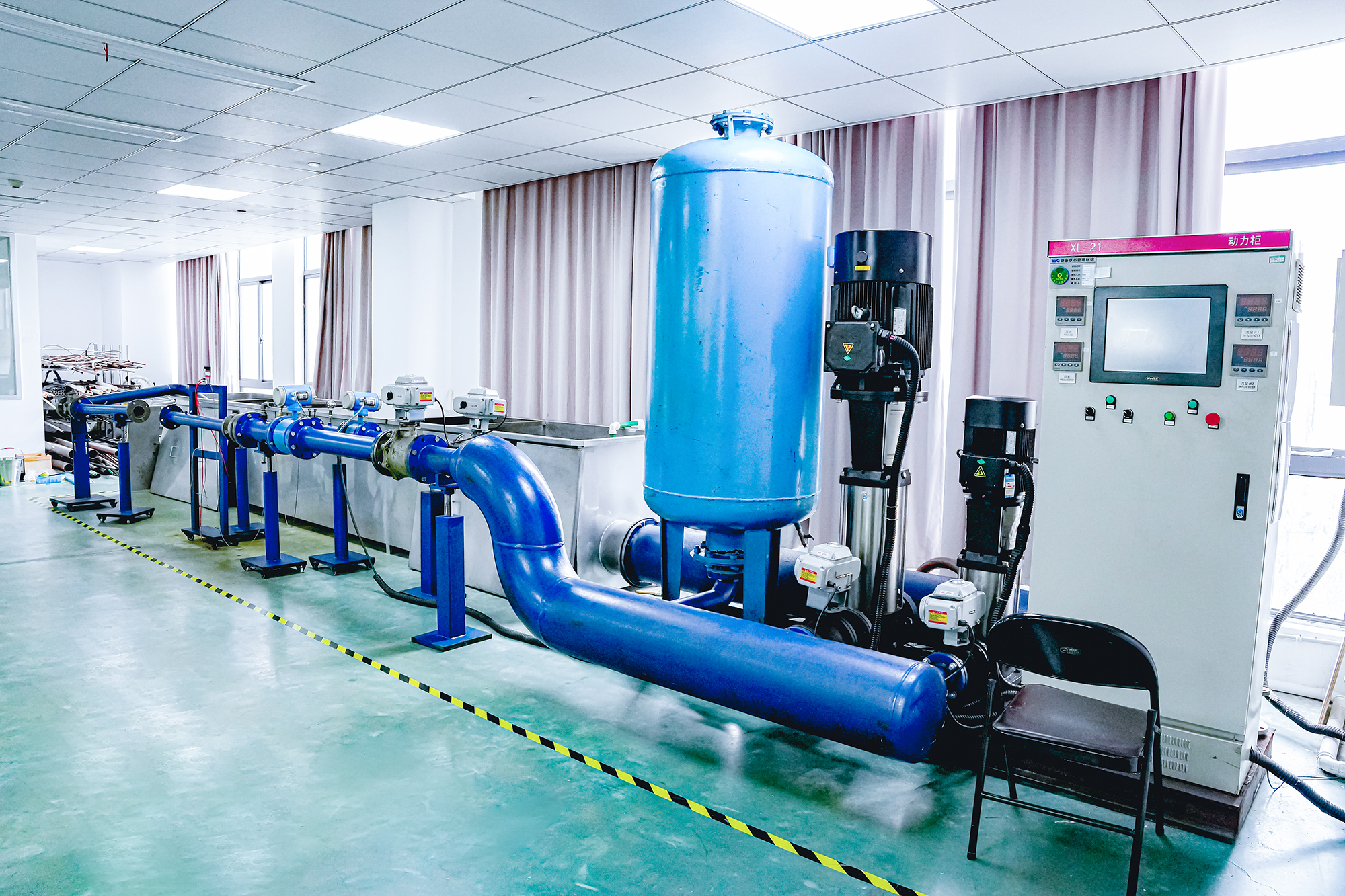
How a buyer should read this: a broad catalogue is easy to demonstrate, and a certificate list is easy to publish. What is harder to demonstrate is that the same valve behaves the same way in lot 40 as it did in lot 1. Automation on the ball and gate lines and an in-house laboratory address that specific question — which is the question that matters when the alternative is a warranty claim inside a finished building.
Market context
The demand side supports the case for treating valve selection as a procurement discipline rather than a commodity purchase. Dataintelo's brass valve market report values the global brass valve market at USD 14.0 billion in 2025 and projects it to reach USD 21.35 billion by 2034. The same source attributes 41% of 2025 global brass valve revenue to Asia Pacific, and forecasts the angle valve segment — the radiator connection valve in a hydronic circuit — growing from USD 1.07 billion in 2026 to USD 1.79 billion by 2035 at a 6.4% annual rate.
Two cautions apply. Published market figures from commercial research houses differ in product boundary — some include fittings and industrial valves, some do not — so they are usable as directional context, not as audited data. And segment-level forecasts carry wider uncertainty than the aggregate: the angle valve forecast above is reported at medium confidence in the underlying source. On the qualitative side, replacement and renovation demand in existing radiator systems, the shift toward lower flow temperatures in heat pump installations, and the growing share of manifold-based underfloor distribution all point the same way: more valves per installation, and more of them doing a specific job rather than a generic one.
Procurement checklist
| Check | What to request | Why it decides the purchase |
|---|---|---|
| Duty match | Written confirmation of which valve type is specified at each position | A ball valve in a throttling position or a gate valve part-open is a built-in callback |
| Rating vs. design conditions | Pressure and temperature rating for the exact model and size | Ranges differ by type: PN10, PN16 and PN40 models coexist in one circuit |
| Thread standard | Declared thread standard (e.g. ISO 228, ISO 7/1 Rp) | Mismatched threads cause leaks that are blamed on the valve |
| Certification scope | Certificate copy showing model, size and market | Market access is granted per item, not per brand |
| Test evidence | Pressure and tightness test records for the batch | Reveals lot-to-lot variation before it reaches site |
| Customisation | Thread specification, surface finish, logo engraving, packaging | Regional market requirements usually sit in these four items |
Future outlook
The direction of travel in hydronic heating favours valves that are selected by function rather than by size alone. Heat pump systems cycle more often than boiler circuits, which shifts attention to cyclic thermal stress and to sealing at low flow rates. Underfloor distribution puts more branches and more isolation points into every installation, and a leak behind a floor build-up is disproportionately expensive to fix. District heating keeps pushing pressure and temperature ratings upward while demanding repeatable manual settings that survive years of no attention.
For buyers, the practical implication is that the specification should name the duty at every position, not just the valve type and size. For suppliers, it means that automation and in-house testing are moving from marketing points to qualification criteria — because the buyer's risk sits in variation between lots, and that risk is only visible through manufacturing evidence.
FAQ
Ball valve, gate valve or stop valve — which one should I use?
It depends on the duty, not on preference. Ball valves give quarter-turn isolation and are the default for on/off duty in water and gas lines, because the handle shows the valve state at a glance. Gate valves open slowly on a multi-turn handwheel and give a straight-through, low-resistance bore, but they are for fully open or fully closed duty only. Stop valves are made for throttling. Use ball for isolation, gate for low-resistance isolation, and stop for regulation.
Does full port or reduced port matter when choosing a brass ball valve?
Yes. A full port ball valve has an internal bore the same size as the pipe, so it adds almost no restriction to flow. A reduced port (standard port) valve has a narrower bore. Full port costs more and takes more space; reduced port is cheaper and more compact but creates a pressure drop. Choose full port where flow matters — pumps, manifolds, low-pressure systems. Choose reduced port where space or cost matters and the pump has spare head.
Why does an underfloor heating system need a mixing valve?
Underfloor heating must run at a much lower flow temperature than radiators — typically 35–45 °C against a boiler or heat pump supply of 55–70 °C — because the floor build-up cannot take the higher temperature. A mixing valve blends hot water from the heat source with cooler water returning from the loops, so the manifold is fed at the design floor temperature whatever the source supplies.
How should a brass underfloor heating manifold be installed?
Fit the manifold in the cabinet with the supply bar above the return bar, connect the heat source to the mixing group, connect each loop pipe to its own outlet, pressure-test the assembly, then fill, vent and set the flow meters. Flush the pipework before connecting anything, and never close the cabinet before the pressure test has passed. The assembly should not be pressurised with the cabinet closed and no way to observe it, and the stated test pressure should not be exceeded.
Further technical detail on the brass valve and manifold range discussed here is available in the Valogin product catalogue: VG brand catalogue (PDF). Manufacturer reference: valve.valogin.com.
Market figures in this article are source-reported by Dataintelo (commercial research, 2025–2034 forecast horizon) and are treated as directional context. Company figures are as reported by Zhejiang Valogin Technology Co., Ltd. Product parameters are as declared for the models named and should be confirmed against the current datasheet and certificate scope before specification.
Есть вопросы или нужны дополнительные детали?
Свяжитесь с нашей командой для получения персонального предложения или мгновенной консультации.
Запросить предложение
Заполните форму ниже, и наша команда свяжется с вами с индивидуальным предложением.
Прямой чат WhatsApp
Предпочитаете общаться в реальном времени? Напишите нам в WhatsApp для мгновенной помощи и быстрых ответов.
- Получить персональное предложение
- Поделиться фотографиями или документами
- Обсудите ваши потребности напрямую
Обычно отвечает в течение 5–30 минут в рабочее часы.