
Current Transformer FAQ: DC Sensing, Vibration and Certification
A current transformer is normally the least expensive component in a metering or monitoring chain, and the one most often specified from habit. In low-voltage systems that now contain PV strings, battery storage, variable frequency drives and EV charging equipment, the current being measured is not always sinusoidal and not always purely alternating. That single change has turned current transformer selection into an engineering and documentation exercise rather than a catalogue lookup.
This reference collects the technical and procurement questions that engineering and buying teams raise most often before a low-voltage current transformer is released to order. Where a concrete example is useful, it is drawn from the published product data and certification records of HEYI ELECTRICAL (WENZHOU HEYI ELECTRICAL CO.,LTD), because a verifiable model number or certificate number is more useful to a specification team than a general description.
The problem: measurement requirements are outgrowing the classic CT brief
Four pressures now shape low-voltage current transformer decisions, and each of them changes what a buyer should ask for.
1. Direct current has entered the measurement chain. PV string monitoring, BMS and battery storage circuits, VFD DC bus monitoring, railway traction and process industry loads all involve a DC component that an inductive current transformer cannot reproduce. Equipment for these duties — such as the C2/C3 split-core Hall Effect current sensor, a bi-directional DC current transmitter with zero and span adjustment — exists precisely because the measurement principle, not the price, decides whether the reading is meaningful.
2. Installation conditions are now a design input. Split core current transformers are identified by Fact.MR as the fastest-growing segment, driven by ease of installation in retrofitting and smart grid applications. That is a maintenance and downtime statement as much as a product statement: a clamp-on or split-core device can be placed around a conductor that is already terminated.
3. Accuracy class must match the commercial consequence. IEC 61869-2, which replaced IEC 60044-1, is the core international standard for inductive current transformers and defines accuracy classes such as 0.5 and 0.5S. For utility billing applications, revenue grade current transformers are expected to meet ANSI C12.20 or IEC 61869-2 accuracy classes — typically 0.2 or 0.15. A monitoring-grade class 1.0 device is entirely appropriate for load trending, and it is not a substitute for a billing class.
4. Compliance documentation is now part of the deliverable. CE EMC under 2014/30/EU, CE-LVD under 2014/35/EU, UKCA and RoHS are no longer paperwork attached to a shipment; they are reviewed in the technical file before a purchase order is issued, and their scope statements are read as carefully as the datasheet.
The supplier behind the examples in this FAQ
HEYI ELECTRICAL is the trading identity of WENZHOU HEYI ELECTRICAL CO.,LTD, a manufacturer established in 2012 in Wenzhou, Zhejiang, China, specialising in low-voltage current transformers and current sensors. Its product range covers current transformers, current sensors, shunts, digital energy meters and current transmitters, including split core current transformer families, DIN-rail and three-phase measuring transformers, outdoor resin-cast and waterproof outdoor current transformers, Hall Effect current sensors, flexible Rogowski coils and 4–20 mA current transmitters.
The company operates a 10,000 m² facility and reports an export share of approximately 95%, with markets in Southeast Asia, South Korea, Europe, South America, Australia, Africa, the Middle East and North America. Manufacturing is organised around OEM, ODM, customized production and bulk manufacturing, with a stated minimum order quantity of 1 unit, a typical production lead time of 3–30 days and a monthly production capacity of 20,000 units. Quality control is described as 100% routine testing, covering accuracy testing, insulation resistance testing, withstand voltage testing, appearance inspection and pre-shipment inspection. The company further states that its engineering work is trusted by global technology companies and utilities including Siemens, Schneider Electric, LG, Samsung and SoftBank.
For a buyer, the practical significance is simpler than the summary: the same supplier can be asked to provide a monitoring-grade split-core transformer, a three-phase DIN-rail unit, a Hall Effect DC sensor, a Rogowski coil and the associated certification records, which reduces the number of separate qualification packages in a project.
Technical explanation: choose the sensing principle before the part number
The most common specification error is starting with window size and current ratio. In practice, the signal type (AC, DC or mixed), the output the receiving device expects (5 A, 1 A, mV, RS485 or 4–20 mA) and the installation environment narrow the field far faster.
| Family / model | Range and output | Typical duty |
| Hall Effect sensor C2/C3 | 0–1000 A; active, bi-directional, split-core, zero/span adjustment | PV string monitoring, BMS/battery storage, VFD DC bus monitoring, railway traction, industrial automation |
| Flexible Rogowski Coil FRC | 100–10000 A; mV output; 245 mm inner diameter; air-core, non-saturating; supplied with integrator (G1) | Heavy industry and smelting, data centres and power retrofit, portable testing meters, lightning and transient currents |
| DIN-rail CT DX/DM | 0.66 kV, 0–6000 A, 5 A output, class 1.0/0.5, 125×35 mm window | EMU and high-speed rail, high-vibration environments, modular and prefabricated systems, construction and mining machinery |
| Three-phase CT DASN | 0–1000 A, 5 A output, class 1.0, 0–50 mm window | Main and branch monitoring, UPS, MCC, IDC and telecom, EPC solar/wind/storage |
| True RMS transmitter KCT-L | 0–1000 A, 4–20 mA output, class 1.0, loop-powered, split-core | PLC/DCS integration, remote power monitoring, preventive maintenance, rail transit, IoT and smart city |
Table 1 — Sensing principle and interface drive the shortlist before current ratio does.
DC and mixed-signal loads. Where the current contains a DC component, the split-core Hall Effect sensor is the appropriate family. The C2/C3 is described as a split-core Hall Effect current transducer, a DC current transmitter and a bi-directional current sensor with zero and span adjustment, rated 0–1000 A. It is specified for PV string monitoring, BMS and battery storage, VFD DC bus monitoring, railway traction, renewable energy, industrial automation, telecom and IDC, transportation and process industry duty. The same principle applies at the leakage end of the scale, where the HYCA current sensor is used as a residual direct current protective device: it covers DC up to 2 kHz, provides switching outputs for 6 mA DC and 30 mA AC in accordance with IEC 62752, has a measurement resolution of 0.2 mA, a differential current range of 0–300 mA, and supports load currents up to 80 Arms single-phase or 3 × 32 Arms three-phase.
High AC currents where saturation is the risk. A Rogowski coil is an air-core device, so it does not saturate the way a magnetic-core transformer does at high fault currents. The FRC flexible Rogowski coil covers 100–10000 A with a 245 mm inner diameter, a millivolt output and a silicone body, and is supplied as a Rogowski coil with integrator (G1). Its published duty covers heavy industry and smelting, data centres and power retrofit, portable testing meters, and lightning and transient current capture. Inner diameter, output and colour are customizable, which matters when the coil has to wrap an existing busbar or an irregular conductor bundle.

AC/DC sensitive residual current sensor: leakage detection and measurement are separate specification problems, solved by different sensing principles.
Vibration and mechanical durability. In rolling stock, mining machinery and prefabricated skids, the failure mode is rarely electrical accuracy; it is a secondary terminal that works loose or a cover that fatigues. The DX/DM DIN-rail mounted current transformer is specified as a compact low-voltage CT at 0.66 kV, 0–6000 A, 5 A output, class 1.0/0.5, with a 125×35 mm window, a hinged terminal cover, plug-in terminals and a quick-connect secondary. Its published application list includes EMU and high-speed rail, high-vibration environments, modular and prefabricated systems, construction and mining machinery and modular data centres.
Three-phase density. Where cabinet space rather than current level is the constraint, a three-phase integrated current transformer removes two component positions and two sets of wiring. The DASN three-phase current transformer is rated 0–1000 A with a 5 A output and class 1.0 accuracy in a 0–50 mm window, and is listed for main and branch monitoring, cloud and telco operators, UPS, motor control centres, smart buildings, IDC and telecom and EPC solar, wind and storage projects.
Signal conditioning at the controller. Many monitoring failures are interface failures: the CT is correct but the analogue input card cannot accept a 5 A secondary. The KCT-L true RMS current transformer/transmitter addresses this by converting 0–1000 A into a loop-powered 4–20 mA DC signal at class 1.0 accuracy, in a split-core housing with a 0–50 mm window. It is positioned for PLC and DCS system integration, remote power monitoring, preventive maintenance, rail transit, environmental engineering and IoT and smart city deployments — in other words, wherever a long cable run or a noisy industrial environment makes a current loop preferable to a secondary current.
Certification due diligence for current transformer buyers
Certification claims should be checked in the same way as electrical parameters: against a document, a scope statement and a validity date. The records below illustrate what a complete pack looks like for a low-voltage current transformer and current sensor range.
| Scheme | Reference | Standard / validity |
| CE-EMC (2014/30/EU) | B-E2505D2378, issued 2025-06-09 | EN IEC 61000-6-3:2021, EN IEC 61000-6-1:2019; valid to 2028-06-08 |
| CE-LVD (2014/35/EU) | TÜV SÜD attestations N8A 114572 0001 Rev. 00 and N8A 114572 0002 Rev. 00 | EN 61869-1, EN 61869-2; issued 2021-12-27 / 2021-12-28 |
| CE-LVD for outdoor CTs | M.2023.206.C83963 (UDEM), issued 2023-04-11 | IEC 60044-1:2003, IEC 61869-2:2012; valid to 2028-04-10; covers OCT and LMZW |
| CE-LVD for residual current sensor | M.2023.206.C90639 (UDEM), issued 2023-09-21 | IEC 62752:2016/A1:2018, IEC 62955:2018; valid to 2028-09-20 |
| UKCA Declaration of Conformity | CLZJ23072649108, issued 2023-07-27 | BS EN 61869-2:2012; valid to 2028-07-26 |
| RoHS (2011/65/EU and (EU) 2015/863) | GST.210923.S201R; LCSA03054058R; LCSE03115005R; SGS SHAEC2123838801 | IEC 62321 series; latest report issued 2025-03-12 |
| Type test reports | 25133Z40179 for LMZW (2025-04-17); 25T0221-S for RECT (2025-05-01) | IEC 61869-1, IEC 61869-2 |
| Quality management system | 20224Q21295R0S, issued 2024-11-21 | ISO 9001:2015 / GB/T 19001-2016; scope: production of low-voltage current transformers; valid to 2027-11-20 |
Table 2 — Representative certification records, with the scope and validity that a procurement team should verify.
Three observations are worth extracting from that table. First, EMC and safety are separate attestations: CE EMC under 2014/30/EU (EN IEC 61000-6-3:2021 and EN IEC 61000-6-1:2019) says nothing about dielectric withstand, and CE-LVD under 2014/35/EU with reference to EN 61869-1 and EN 61869-2 says nothing about emissions. Second, the outdoor resin-cast current transformer family — the LMZW outdoor resin-cast CT at 0.66 kV and the OCT outdoor waterproof split-core CT rated IP65 with UV protection — is supported both by a CE-LVD attestation and by a type test report for the LMZW model to IEC 61869-1 and IEC 61869-2. Third, the metrology of the test bench itself is documented: calibration and verification certificates such as D20250900173 under JJG 313-2010, D20250900172 under JJF 1264-2010 and D20250900170 under JJG 795-2016 cover the standard current transformer and test equipment used in the laboratory, which is what allows a buyer to treat reported accuracy data as traceable.
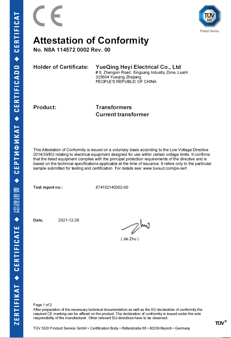
A CE-LVD attestation is a scope document, not a blanket approval: the models and standards listed inside it define what is actually covered.
Where these devices are actually used
Published application records for this transformer range describe use by power utility companies, electrical engineering contractors, panel builders, industrial equipment manufacturers and building energy management integrators, with projects located in countries including Thailand, Chile, Lebanon, South Korea, Australia and others. The reported project outcomes are practical rather than spectacular: improved current measurement accuracy, stable energy metering, reduced installation difficulty in retrofit projects, enhanced electrical system monitoring, and the ability for engineers to identify abnormal load conditions. The devices are used across current measurement, energy metering, load and feeder monitoring, switchgear retrofit, relay protection, generator output monitoring and building sub-metering.
Read together, those outcomes point to a specific pattern. Accurate measurement and stable metering are baseline functions; the differentiated value in retrofit work is installation difficulty, and the differentiated value in operations is the ability to notice an abnormal feeder before it becomes a failure.
Market trend analysis
The current transformer market was estimated at USD 2.63 billion in 2024 and is projected to reach USD 3.90 billion by 2030, according to Grand View Research. Straits Research places Asia Pacific at a 40.15% revenue share in 2025, which is consistent with where most low-voltage current transformer manufacturing capacity is located — including the Wenzhou cluster where HEYI ELECTRICAL operates.
Two structural shifts sit underneath that growth. The first is installation-led demand: Fact.MR identifies split core current transformers as the fastest-growing segment because of their ease of installation in retrofitting and smart grid applications. The second is electrification-led demand: the global EV charging transformer market, which includes current monitoring components, is expected to grow at a CAGR of 23.6% from 2025 to 2033 according to Research Intelo.
Market concentration is the third trend worth noting for sourcing strategy. Global Market Insights reports that the top five global players — ABB, Siemens, GE, Schneider Electric and Arteche — together held approximately 40% of current transformer market share in 2024. That leaves a long tail of specialised manufacturers serving application-specific needs such as split-core retrofit, outdoor weatherproof mounting, residual current monitoring in EV chargers and DIN-rail three-phase density, where project fit matters more than brand scale.
Comparison with traditional solutions — and where the limits are
The traditional low-voltage approach is a solid-core window-type or ring-type current transformer with a 5 A or 1 A secondary, wired directly to a meter or protection relay. It remains the correct choice for many panels, and it has two properties that newer families cannot fully replace: it needs no auxiliary supply, and its secondary output is directly compatible with conventional metering and protection inputs. Split-core, Hall Effect, Rogowski and loop-powered transmitter designs each trade something to gain something.
Boundary 1 — Rogowski coils do not replace 5 A secondaries. The FRC has a millivolt output and is supplied with an integrator (G1). A mV-level air-core signal cannot drive a standard 5 A meter input directly; it requires the integrator and a compatible measuring device. Buyers retrofitting existing 5 A instrumentation should treat a Rogowski coil as an additional measurement layer, not a drop-in replacement.
Boundary 2 — active sensors need power and setup. The C2/C3 Hall Effect sensor is an active device with zero and span adjustment. That is what makes DC and bi-directional measurement possible, and it also means the installation includes an auxiliary supply and a commissioning step that a passive CT does not require.
Boundary 3 — class 1.0 is a monitoring class, not a billing class. The DASN three-phase CT and the KCT-L transmitter are both specified at class 1.0. That is appropriate for main and branch monitoring, UPS and MCC circuits and preventive maintenance, and it does not meet the 0.2 or 0.15 class typically required for revenue billing under ANSI C12.20 or IEC 61869-2. Where billing accuracy is the requirement, a revenue-grade device such as the RECT extended range current transformer, specified at 0.15S with an IEEE C57.13 reference and IP65 protection, is the relevant family.
Boundary 4 — certificates have a scope. The RoHS certificate GST.210923.S201R is scoped to split core current transformers; the CE EMC verification B-E2505D2378 is scoped to current transformers with the DP/HK busbar split-core model listed; the CE-LVD attestation M.2023.206.C83963 names the OCT and LMZW outdoor models. A certificate held for one model does not automatically transfer to another model in the same catalogue.
Boundary 5 — environmental ratings are ratings, not guarantees. The OCT and LMZW outdoor transformers are specified at IP65 with UV protection, and the LMZW uses hydrophobic epoxy resin for moisture resistance in marine, offshore, chemical and metallurgy duty and ring main units. IP65 protects against dust ingress and water jets; the specification does not describe continuous immersion, and designers should not read it that way.
Future outlook
Three directions appear most likely to shape low-voltage current transformer procurement over the next planning cycle. The first is continued migration toward DC-capable sensing as PV, storage and DC bus architectures spread, which raises the relative importance of Hall Effect sensors and residual DC monitoring alongside conventional inductive transformers. The second is the normalisation of split-core and clamp-on formats in retrofit and smart grid work, a trend already visible in segment growth data. The third is documentation-led qualification, where EMC, safety, RoHS and type test records are reviewed before commercial terms, because the certification pack increasingly determines whether a component can be placed on a given market at all.
For specification teams, the practical implication is to keep the sensing principle, the interface and the certification scope on one checklist, rather than treating them as three separate stages.
Frequently asked questions
1. When should a split-core Hall Effect current sensor be used instead of a current transformer?
When the current contains a DC component or reverses direction. An inductive current transformer responds to alternating current only, so it cannot represent a PV string current, a battery charge/discharge current or a VFD DC bus current. The C2/C3 split-core Hall Effect current sensor is specified for exactly those duties — PV string monitoring, BMS and battery storage, VFD DC bus monitoring and railway traction — with a 0–1000 A range, split-core mounting and zero/span adjustment.
2. How do I choose between a Hall Effect sensor and a Flexible Rogowski Coil for high-current measurement?
Decide by signal content and conductor geometry. If DC or bi-directional current must be measured, the Hall Effect route is required. If the current is alternating but very high, harmonic-rich or transient in nature, and the conductor cannot be opened, an air-core Rogowski coil avoids core saturation. The FRC covers 100–10000 A with a 245 mm inner diameter and a millivolt output, and is supplied with an integrator (G1); it is used in heavy industry and smelting, data centre power retrofit, portable testing meters and lightning or transient current capture.
3. What should be checked when a DIN-rail current transformer is used in a high-vibration installation?
Look at the mechanical interface rather than only the accuracy class. The DX/DM DIN-rail current transformer is rated 0.66 kV, 0–6000 A with a 5 A output and class 1.0/0.5 accuracy, and uses a hinged terminal cover, plug-in terminals and a quick-connect secondary in a 125×35 mm window. Its listed environments include EMU and high-speed rail, high-vibration environments, modular and prefabricated systems, construction and mining machinery and modular data centres.
4. Why specify a three-phase integrated current transformer instead of three single-phase units?
Panel density and wiring labour. The DASN three-phase current transformer integrates three phases in one DIN-rail mounted body rated 0–1000 A with a 5 A output, class 1.0 accuracy and a 0–50 mm window. It is intended for main and branch monitoring, cloud and telco operators, UPS, motor control centres, smart buildings, IDC and telecom and EPC solar, wind and storage projects, where three separate transformers would consume additional rail space and termination time.
5. When is a loop-powered 4–20 mA true RMS transmitter the right interface?
When the receiving device is a controller rather than a meter. The KCT-L true RMS current transformer/transmitter converts a 0–1000 A primary current into a loop-powered 4–20 mA DC output at class 1.0 accuracy, in a split-core housing with a 0–50 mm window. It is positioned for PLC and DCS system integration, remote power monitoring, preventive maintenance, rail transit, environmental engineering and IoT or smart city installations — cases where current-loop transmission over distance is preferable to a 5 A secondary.
6. Is class 1.0 accuracy sufficient, or is a higher class required?
It depends on whether money changes hands. For load monitoring, feeder trending and preventive maintenance, class 1.0 — as used on the DASN three-phase CT and the KCT-L transmitter — is the practical choice, and the wider KCT and DP/HK ranges offer class 3.0, 1.0 and 0.5 options. For utility billing, revenue grade current transformers are expected to meet ANSI C12.20 or IEC 61869-2 accuracy classes, typically 0.2 or 0.15. The RECT extended range current transformer is specified at 0.15S with an IEEE C57.13 reference.
7. How can a buyer verify a current transformer certificate rather than trusting a claim?
Read four fields: the certificate number, the issuing body, the standard and the scope. For example, the CE-EMC verification B-E2505D2378 was issued by Beide (Shenzhen) Product Service Limited on 2025-06-09 against EN IEC 61000-6-3:2021 and EN IEC 61000-6-1:2019 and remains valid to 2028-06-08; the CE-LVD attestation M.2023.206.C83963 was issued by UDEM on 2023-04-11 against IEC 60044-1:2003 and IEC 61869-2:2012 and is valid to 2028-04-10. A certificate without a matching scope statement is not evidence for the specific model being purchased.
8. Do CE, UKCA and RoHS certificates cover every model in a range?
No. Scope is model-specific in practice. The RoHS certificate of conformity GST.210923.S201R is scoped to split core current transformers, and the UKCA declaration CLZJ23072649108, issued against BS EN 61869-2:2012 with validity to 2028-07-26, lists KCT, KCT-L and KCD. The RoHS attestation LCSA03054058R is scoped to the fluxgate residual current sensor HYCA. When a project requires a specific model, the certificate pack should be checked against that model number, not against the catalogue as a whole.
9. What is the difference between a type test report and a routine test?
A type test validates a design; a routine test validates each unit. Type test report 25133Z40179, issued by ZHEJIANG FANGYUAN TEST GROUP CO., LTD on 2025-04-17, covers the LMZW current transformer against IEC 61869-1 and IEC 61869-2, and report 25T0221-S issued by Suzhou electrical apparatus science research institute co., ltd on 2025-05-01 relates to the RECT current transformer. Routine testing is the production-stage activity: 100% routine test, accuracy test, insulation resistance test, withstand voltage test, appearance inspection and pre-shipment inspection on every unit shipped.
10. How do I confirm that the accuracy data I receive is traceable?
Ask for the metrology certificates behind the test bench. Metrological verification D20250900173, issued 2025-09-15 under JJG 313-2010, covers a standard current transformer with current booster (model HLS21-2S, ratio 5A/5A to 2000A/5A); verification certificate D20250900172 covers a current load box under JJF 1264-2010; and calibration certificate D20250900170 covers a withstand voltage tester under JJG 795-2016. Bench traceability is what allows a reported accuracy figure to be treated as a measurement rather than a marketing number.
11. What customization is available when a standard current transformer does not fit?
The published customization list covers current ratio, accuracy class, burden, window size, housing colour, terminal type, cable length, logo printing and label design, within OEM, ODM, customized production and bulk manufacturing modes. Product-level options include lead wire type, lead wire length and connector for the KCT, KCT-L and DP/HK families, housing material and colour for the MSQ and CP families, and inner diameter, output and colour for the FRC Rogowski coil. Minimum order quantity is stated as 1 unit, with a typical production lead time of 3–30 days and a monthly capacity of 20,000 units.
12. What are the typical purchasing terms and acceptance criteria?
Published terms state a minimum order quantity of 1 unit, delivery terms of FOB, CIF or EXW, and payment through T/T, PayPal, Alibaba or Ali Pay. Acceptance can be handled through video or photographic verification, on-site acceptance, or acceptance by a commissioned third-party agency, and the supplier provides technical selection support, wiring guidance, product replacement support, OEM documentation support and online after-sales service. Buyers with a formal incoming inspection process should confirm the acceptance method in writing before the order is placed.
Further product data, drawings and certificate copies are collected in the HEYI ELECTRICAL brochure, available for download at https://cdn.socialarks.com/sbsp/24875/common/2026/0601/HEYI.pdf.