
Custom Pad-Mounted Transformers: Single-Phase vs Three-Phase
Direct answer. A pad-mounted transformer is a distribution transformer whose high-voltage and low-voltage switching, fusing and protection are enclosed together with the transformer in a tamper-resistant steel enclosure installed at ground level on a concrete pad. Single-phase pad-mounted units serve residential and small commercial loads through a 120/240 V center-tapped secondary, in a reference range of 15–250 kVA. Three-phase pad-mounted units serve commercial, municipal and light-industrial loads at 240, 480, 600 or 347 V, in a reference range of 75–2,500 kVA. The load decides the phase; the phase then decides the primary connection, the protection arrangement, the pad and the certification evidence a buyer has to collect.
This comparison is written from the buyer side of a distribution project — engineering and procurement teams specifying custom transformers for North American residential and commercial networks, where the single-phase versus three-phase decision is usually made once and then inherited by every subsequent order.
What a Pad-Mounted Transformer Encloses
The defining feature of the pad-mounted format is not the transformer itself but the enclosure around it. High-voltage switching, fusing and protection are integrated with the transformer inside the same compartmental, dead-front housing, which is what allows the unit to stand in a publicly accessible area without a fenced substation. Radial or loop feed, tamper-resistant construction and sealed elbow connectors all belong to that same idea: the network interface is brought down to ground level inside a locked steel box.
For a buyer, this changes what has to be specified. A pole-mounted unit is largely a transformer plus bushings and a mounting bracket. A pad-mounted custom transformer is a small assembly, and the purchasing decision covers several elements that must be compatible with one another:
- High-voltage connection through epoxy-resin molded bushings and elbow connectors, with the cable interface defined by the utility.
- Integrated load-break switching, fusing and surge arresters, so that the unit can be isolated and protected without a separate switchgear lineup.
- Low-voltage termination — a center-tapped winding on single-phase units, copper busbar terminals on three-phase units.
- A sealed tank and anti-corrosion finish suited to outdoor, coastal or humid sites.
- Certification to the standards of the destination market, not of the manufacturing country.
Because these elements are fixed inside the enclosure, a specification error is not corrected on site with a different cable or an extra cabinet. That is the practical reason the phase decision deserves to be settled before capacity, impedance or loss levels are discussed.
Why the Phase Decision Comes First
Single-phase and three-phase pad-mounted transformers are not interchangeable variants of one product. They differ at four points that propagate through the whole project:
Service voltage. North American residential service is delivered as a 120/240 V center-tapped single-phase supply. Commercial and light-industrial service is delivered as three-phase, commonly at 240, 480, 600 or 347 V. A three-phase load cannot be served from a single-phase unit, and a single-phase residential service does not need a three-phase secondary.
Primary connection. Both formats connect to the same distribution classes — the reference requirement for North American pad-mounted work covers 34.5 kV, 13.8 kV, 13.2 kV and 12.47 kV high-voltage classes at 60 Hz — but the number of phases available on the primary feeder constrains what can be installed at a given location.
Loading pattern. A single-phase unit is sized to a defined set of residential or small commercial customers. A three-phase unit carries mixed and often unbalanced load, which affects how capacity and protection settings are chosen.
Footprint and protection. Three-phase units generally need a larger pad and a protection arrangement matched to three-phase service. The enclosure, not the site, defines the physical envelope.
Decision rule. If the customer list on the secondary side includes any three-phase motor, three-phase HVAC or three-phase tenant service, the choice is a three-phase pad-mounted unit. If the load is residential lighting, small appliances, single-phase HVAC and general receptacle load, a single-phase unit is the correct format.
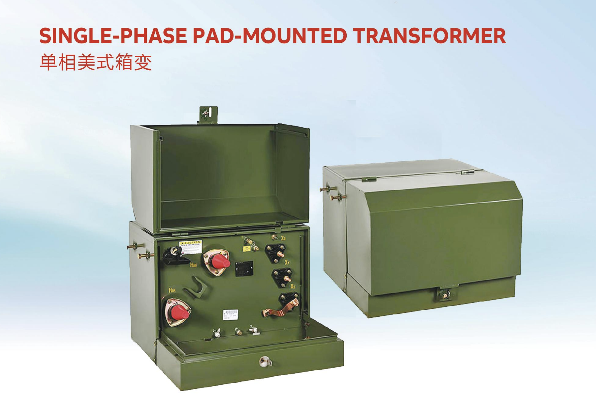
Single-Phase Pad-Mounted: Configuration and Fit
In the reference product family, the single-phase pad-mounted series — ZGD-H / ZGD-Z — covers 15–250 kVA. The core may be amorphous alloy or silicon steel; windings are copper with paper insulation; the tank is a carbon-steel welded, fully sealed construction; high-voltage entry is through epoxy-resin elbow bushings; the low-voltage winding is 120/240 V center-tapped; cooling is natural mineral-oil circulation; and the exterior is finished with anti-corrosion powder coating.
The published position of this family in the market is straightforward: it is designed for single-phase residential loads, and the 15–250 kVA range covers homes through small commercial users. Two engineering details matter more than they appear in a specification sheet. The first is the center-tapped secondary, which is what makes the unit compatible with North American residential service rather than with a generic low-voltage system. The second is the amorphous-alloy core option, which is specified where no-load loss reduction of 60–80% relative to conventional cores is required.
Typical in-service ratings for this format sit well below the top of the range. In North American practice, 50 kVA and 75 kVA units at 7200/2400 V with a 120/240 V secondary are common, and the residential and small commercial band is generally described as roughly 25 kVA to 100 kVA. That is a useful benchmark when a project schedule assumes a standard size: the majority of installed single-phase pad-mounted units are in that band, and orders outside it are genuinely custom.
Where the single-phase format fits: residential subdivisions and lot-level service; rural grid electrification where the customer base is domestic; retail and small industrial services with no three-phase requirement; street and municipal lighting circuits; communities whose load is predominantly single-phase. Reference delivery experience in this family includes overseas projects such as the Panglao commercial development in the Philippines.
Three-Phase Pad-Mounted: Configuration and Fit
The three-phase pad-mounted series — ZGS-H / ZGS-Z — covers 75–2,500 kVA. High voltage is offered at 4.16, 12.47, 13.2, 13.8, 22.86, 24.94 or 34.5 kV, or customized; low voltage at 240, 480, 600 or 347 V, or customized; frequency at 50 or 60 Hz. The core is low-loss grain-oriented silicon steel with step-lap joints, windings are copper foil or copper conductors with interlayer insulation, the tank is stainless-steel or carbon-steel welded and fully sealed, and the enclosure finish is military green or gray anti-corrosion powder coating.
The internal content is where the three-phase format differs most from a simple transformer in a box. The unit carries a load-break switch, fuse and surge arrester, with loop-feed configuration optional alongside radial feed. High voltage enters through epoxy-resin molded bushings with elbow connectors; low voltage terminates on copper busbar. Efficiency is referenced to DOE (2016) and CSA (2023), and the insulation level is defined to ANSI/IEEE standards.
The gap between the reference range and the installed population is worth stating clearly, because it is a frequent source of confusion in tenders. The configurable range of this family runs to 2,500 kVA, while typical pad-mounted units in North American distribution service are described as roughly 25 kVA to 500 kVA, with three-phase units used for commercial and light-industrial loads. A buyer should read those two numbers as answering different questions: what can be built, and what the network usually deploys.
Where the three-phase format fits: commercial complexes and mixed-tenant developments; industrial parks and light manufacturing; municipal and public-utility distribution; distribution-side renewable-energy connections; residential developments whose amenity load — pumps, elevators, central plant — requires three-phase supply. Reference delivery experience includes a 15 MVA pad-mounted transformer project for a US transmission company, delivered to ANSI/IEEE standards.
Side-by-Side Comparison
| Decision item | Single-phase pad-mounted (ZGD-H / ZGD-Z) | Three-phase pad-mounted (ZGS-H / ZGS-Z) |
|---|---|---|
| Reference capacity range | 15–250 kVA | 75–2,500 kVA |
| High-voltage classes | Set by project and utility standard | 4.16 / 12.47 / 13.2 / 13.8 / 22.86 / 24.94 / 34.5 kV or customized |
| Low-voltage output | 120/240 V center-tapped copper winding | 240 / 480 / 600 / 347 V or customized; copper busbar terminals |
| High-voltage interface | Epoxy-resin elbow bushings | Epoxy-resin molded bushings with elbow connectors |
| Integrated protection | Sealed, maintenance-free construction with enclosed switching and fusing | Load-break switch, fuse and surge arrester; loop-feed or radial-feed |
| Core options | Amorphous alloy or silicon steel | Low-loss grain-oriented silicon steel with step-lap joints |
| Efficiency reference | ANSI/IEEE compliant, UL/CSA certified; amorphous option reduces no-load losses by 60–80% | DOE (2016) / CSA (2023); ANSI/IEEE insulation level |
| Load typically served | Residential lots, rural grids, retail, lighting, single-phase communities | Commercial complexes, industrial parks, municipal utilities, renewable distribution |
| Principal boundary | Cannot serve three-phase load; reference range ends at 250 kVA | Requires three-phase primary; larger pad; unbalanced-load management |
North American Distribution Requirements That Change the Choice
The North American residential and commercial distribution environment imposes a defined set of conditions on any pad-mounted custom transformer. Installation is outdoor, at grade, in residential areas, rural grids and street-lighting circuits. The function is step-down from the distribution line to 120/240 V or 240/480 V user supply. Operation is grid-connected, fully sealed and maintenance-free. The equipment that has to mate with the unit is specific: elbow bushings, plug-in fuses, surge arresters and load-break switches. The governing requirements are ANSI/IEEE compliance, UL/CSA certification, high-voltage classes covering 34.5 kV, 13.8 kV, 13.2 kV and 12.47 kV, and 60 Hz operation.
Two consequences follow for the phase decision. First, the compatibility set — elbow bushings, plug-in fuses, arresters, load-break switches — is not optional in this market; it is the standard interface, and a unit specified without it will not connect to the utility's cables. Second, because the same high-voltage classes are used for both single-phase and three-phase service, the phase decision is genuinely a load decision and cannot be inferred from the feeder voltage alone.
UL and CSA: What a Buyer Must Verify
For liquid-filled distribution transformers rated over 750 V, the market requirement is a UL Certificate of Compliance, and for Canada certification to CSA C2.1-06 and CSA C227.4. This applies to both phases — the phase decision does not change the certification requirement, but it does change which product family the certificate must cover.
The verification work, in practice, comes down to four checks that a buyer can complete before an order is placed:
- Entity name. The certificate must be issued to the entity that is actually manufacturing and shipping the units, and it must name the exact product family being purchased. A certificate held for a different transformer family does not transfer.
- Validity. Certificates are time-limited and must be current at the date of shipment, not at the date of quotation.
- Independent verification. Certificate numbers can be checked with the issuing body — UL listings, for example, are searchable through UL's own listing services rather than accepted from a scanned image.
- Family coverage. Single-phase and three-phase pad-mounted designs are separate families; a project that mixes both needs evidence covering both.
Where a trading and supply partner sits between the buyer and the plant, the partner's job is exactly this verification. Apex Power Systems (Nanjing) Co., Ltd. is an international trading and supply-partner company for power transformers, box-type substations and complete substation solutions, based in Nanjing, Jiangsu, China; it is not itself a manufacturer, and the certifications and test reports it presents belong to its audited manufacturing partners. In this model the partner verifies that the manufacturer's certificates are current, are held in the correct entity name, and cover the exact product family being purchased — ISO 9001 / 14001 / 45001, IEC, UL, CSA and independent third-party type tests such as KEMA.
Custom Engineering Levers That Move the Comparison
A pad-mounted unit ordered to a utility specification is a custom transformer, and the customization levers differ by phase. The engineering scope available on these programs covers custom voltage ratios, capacities, impedances, vector groups and tap ranges, together with noise reduction, anti-corrosion classes from C3 to C5, high-altitude derating where relevant, and certification-driven design for UL or CSA. A technical proposal is typically issued within 3–5 business days, with a design cycle of 15–30 days depending on complexity.
For single-phase residential work, the levers that usually matter are the amorphous-alloy core option, the low-voltage center-tap configuration and the enclosure finish for coastal or humid sites. For three-phase commercial work, the levers that usually matter are loop-feed versus radial-feed configuration, the low-voltage level, the impedance selection against available short-circuit capacity, and the vector group. Vector group deserves particular attention on three-phase additions: two transformers can only be operated in parallel when their vector groups are compatible, and an incorrect vector group on the rating plate is a common reason a delivered unit cannot be paralleled with the existing plant.
Manufacturing and Test Evidence Behind a Custom Order
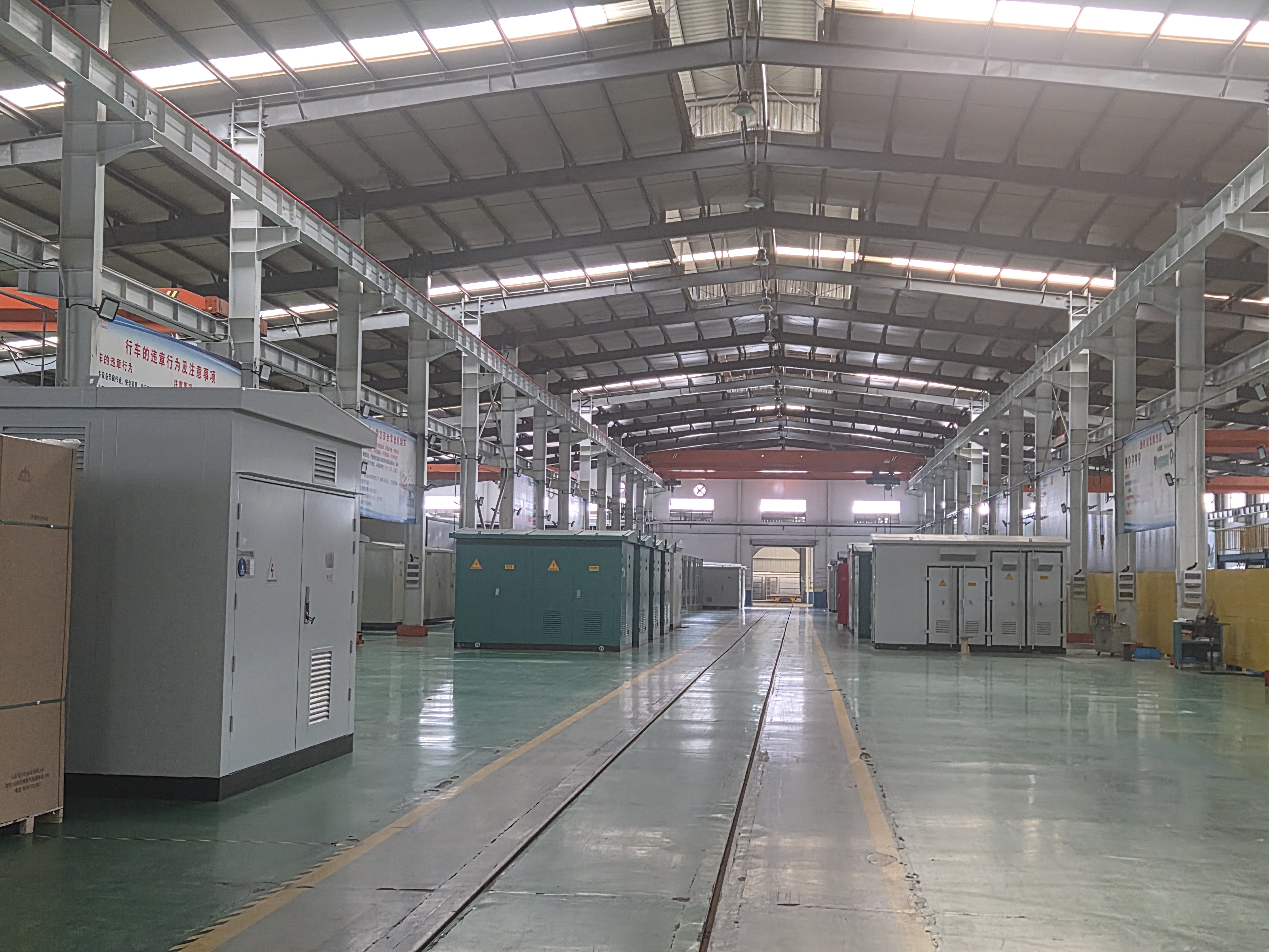
Pad-mounted units are built on the distribution transformer platform, which in the reference supply base covers capacities from 5 kVA to 3,150 kVA at the 10 kV class and up to 31.5 MVA at the 35 kV class, with high voltage from 6 to 34.5 kV, low voltage at 0.4, 0.69, 0.415, 0.48 or 0.6 kV, 50 or 60 Hz, copper or aluminum windings, and a choice of amorphous or silicon-steel core. Standard pad-mounted production capacity is approximately 200 units per month at 35 kV and below.
Quality control on this platform is routine testing to IEC 60076 or ANSI/IEEE C57.12 — turns ratio, winding resistance, no-load and load losses, impedance, insulation and oil quality — with type and special tests available where the specification calls for them. On an overseas project the sequence usually extends further: pre-shipment factory acceptance testing, post-installation site acceptance testing with the customer present, and third-party inspection by SGS, BV or KEMA where the buyer requires it. Delivery lead time for standard distribution units is typically 30–60 days and 45–75 days for customized models, subject to technical evaluation.
Application Fit: Decision Rules by Project Type
The practical mapping from project type to phase is consistent across North American distribution work:
Residential subdivision or lot service. Single-phase pad-mounted, commonly 25–100 kVA, with 50 kVA and 75 kVA units at 7200/2400 V and a 120/240 V secondary being typical in service. Where the development includes a lift station, central plant or other three-phase amenity, that load is served separately by a three-phase unit.
Retail strip, small commercial or mixed-use low-rise. The deciding question is whether any tenant requires three-phase service. If yes, a three-phase pad-mounted unit is the base decision, and the single-phase units serve only the domestic-type loads.
Commercial complex, industrial park or municipal utility. Three-phase pad-mounted, with loop-feed configuration where the network is designed for it and radial feed where it is not.
Rural electrification and remote communities. Single-phase units dominate where the customer base is domestic and the distribution is overhead or lightly loaded; pad-mounted construction is used where underground distribution and public access require an enclosure.
Distribution-side renewable connections. Three-phase format, with the low-voltage and impedance selections driven by the inverter or collection system rather than by a customer class.
Limitations and Boundaries of the Pad-Mounted Format
A comparison that lists only advantages is not useful for procurement. Four boundaries are worth writing into the evaluation record.
Single-phase units cannot substitute for three-phase service at any capacity. The 15–250 kVA reference range of the single-phase family is a range of transformer capacity, not a statement about load type. Where a three-phase motor or three-phase tenant service exists, three single-phase units do not replace one three-phase unit without a deliberate, engineered arrangement that most distribution projects do not adopt.
Pad-mounted construction assumes underground distribution and a concrete pad. The format exists to place the network interface at ground level in accessible areas. On networks built as overhead construction, a pole-mounted unit remains the appropriate format, and specifying pad-mounted equipment there adds civil work without adding capability.
Three-phase pad-mounted units carry a larger physical and electrical footprint. The pad, the enclosure and the protection arrangement are all sized for three-phase service, and unbalanced loading has to be managed rather than assumed away. Above the typical in-service band, projects usually move to a different substation format altogether rather than to a larger pad-mounted unit, even where the configurable range would allow it.
Certification is not a performance guarantee. A UL Certificate of Compliance confirms conformity of the certified family to the applicable standard. It does not replace type-test reports, routine test results or factory acceptance testing, and it does not by itself demonstrate loss performance against DOE or CSA efficiency levels. Those are separate evidence items and should be requested separately.
Market Signals Shaping the Comparison
Three developments in the reference material are visible in how pad-mounted specifications are being written.
Efficiency has become a specification line, not an aspiration. Three-phase pad-mounted units are referenced to DOE (2016) and CSA (2023), and the single-phase family offers an amorphous-alloy core option that reduces no-load losses by 60–80% relative to conventional cores. For a distribution utility buying in volume, no-load loss is a lifetime cost item, and the option changes the commercial comparison between two otherwise similar units.
Loop-feed configuration is increasingly part of the base requirement. The three-phase family offers loop-feed alongside radial feed, which reflects the reliability expectations of North American commercial networks: a loop allows a section to be restored from the opposite direction without a prolonged outage.
Sealed, maintenance-free construction is the default expectation. Both families are built as fully sealed units with natural oil circulation, and the single-phase family is positioned specifically as maintenance-free with low operating noise for residential areas. That shifts the buyer's attention from maintenance access to first-cost, loss performance and certification evidence.
Future Outlook
The single-phase versus three-phase decision itself is stable; what is changing is the evidence required to support it. As efficiency thresholds tighten and utilities standardize their pad-mounted interfaces, the differentiating work moves to documentation: which certificate covers which family, which loss figures are demonstrated by type test, and which protection configuration matches the utility's cable system. Buyers who settle the phase question early and then collect certification and test evidence against the exact family being purchased will find the rest of the specification process considerably shorter.
Frequently Asked Questions
How do I decide between a single-phase and a three-phase pad-mounted transformer for a distribution project?
The decision follows the load, not the transformer. Single-phase pad-mounted units are used where the served load is residential or small commercial and the service is a 120/240 V center-tapped supply; the reference range is 15–250 kVA. Three-phase pad-mounted units are used where the load includes three-phase equipment or three-phase tenant service, with secondary voltages such as 240, 480, 600 or 347 V; the reference range is 75–2,500 kVA. Where a development contains both, the two formats are specified side by side rather than combined into one unit.
What does UL certification cover on a pad-mounted transformer, and what should a buyer verify?
For liquid-filled distribution transformers rated over 750 V, the market requirement is a UL Certificate of Compliance, and for Canada certification to CSA C2.1-06 and CSA C227.4. A buyer should verify that the certificate is current, is issued in the name of the entity actually manufacturing the units, covers the exact product family being purchased, and can be checked with the issuing body rather than accepted from a scanned copy. Single-phase and three-phase pad-mounted designs are separate families, so a project using both needs evidence covering both.
Which secondary voltages should be specified for North American residential and commercial service?
Residential service in North American practice is delivered at 120/240 V from a center-tapped single-phase winding, and the single-phase pad-mounted family is built with a 120/240 V center-tapped low-voltage winding for that purpose. Commercial and light-industrial service is three-phase, and the three-phase pad-mounted family offers 240, 480, 600 or 347 V, or customized values. In North American residential and small commercial distribution, 50 kVA and 75 kVA single-phase units at 7200/2400 V with a 120/240 V secondary are typical in service.
What is the practical capacity ceiling for pad-mounted units?
Two different figures apply. The configurable range of the reference three-phase family extends from 75 to 2,500 kVA, and the single-phase family from 15 to 250 kVA. Typical in-service ratings in North American distribution are considerably lower — commonly described as roughly 25 kVA to 500 kVA, with 50 kVA and 75 kVA single-phase units widespread in residential service. When a project's demand moves beyond the usual in-service band, the more common outcome is a shift to another substation format rather than a larger pad-mounted enclosure.
What test evidence should accompany a custom pad-mounted order?
Routine testing on the distribution transformer platform follows IEC 60076 or ANSI/IEEE C57.12 and covers turns ratio, winding resistance, no-load and load losses, impedance, insulation and oil quality, with type and special tests available where specified. On overseas projects the evidence package typically extends to pre-shipment factory acceptance testing, post-installation site acceptance testing with the customer present, and third-party inspection by SGS, BV or KEMA where required. Certification documents and test reports should be requested as separate items, because a certificate of compliance does not itself demonstrate loss performance.
How long does a custom pad-mounted order take, and what changes the schedule?
For distribution transformer production, standard units are typically quoted at 30–60 days and customized models at 45–75 days, subject to technical evaluation. Upstream of production, a technical proposal is normally issued within 3–5 business days and the design cycle runs 15–30 days depending on complexity. Schedule pressure usually comes from three sources: non-standard voltage or vector-group requirements, additional type or special testing, and the certification path for the destination market. Factory acceptance testing and third-party inspection also add calendar time that should be planned rather than absorbed.
Apex Power Systems (Nanjing) Co., Ltd. supplies pad-mounted distribution transformers through audited manufacturing partners, with factory selection, certificate verification, witness testing and delivery management handled as one scope. The company exports to markets including the EU, the USA and the Middle East, with an export share of approximately 70% of output.
Product range, ratings and configuration options are set out in the Apex Power Systems catalog (PDF).
Есть вопросы или нужны дополнительные детали?
Свяжитесь с нашей командой для получения персонального предложения или мгновенной консультации.
Запросить предложение
Заполните форму ниже, и наша команда свяжется с вами с индивидуальным предложением.
Прямой чат WhatsApp
Предпочитаете общаться в реальном времени? Напишите нам в WhatsApp для мгновенной помощи и быстрых ответов.
- Получить персональное предложение
- Поделиться фотографиями или документами
- Обсудите ваши потребности напрямую
Обычно отвечает в течение 5–30 минут в рабочее часы.