
Die Casting Die Springs: Standards and Selection Limits
Die casting dies close under load, eject hot, and cycle continuously. Those three conditions decide which properties of a die spring actually matter, and they explain why a spring that performs well in a light stamping tool can fail early in a die casting die of similar size. This industry reference sets out the constraints that govern die casting die spring selection: the standard systems that define interchangeability, the load-class colour conventions that are most often misread, the material and heat-treatment facts behind fatigue life, and the limits that no catalogue value removes.
The Duty Profile Inside a Die Casting Tool
Die casting tooling belongs to a wider group of applications, including automotive stamping dies, plastic injection molds, heavy machinery manufacturing, precision electronics stamping and industrial automation equipment, that share a recognisable spring duty profile: high-frequency cyclic shock, continuous high-temperature exposure, high-load compression, contact with oil and coolants, and extreme dynamic stress. Within that profile a die spring performs four jobs. It provides a precise return stroke, absorbs energy in a compact space, damps vibration, and maintains force balance while the die opens and closes. Its motion is reciprocating high-frequency axial compression, normally under continuous preload.
Two consequences follow. First, the spring is a wear part inside a tolerance-critical assembly: it operates in die sets that use guide posts and bushings, sometimes alongside nitrogen spring auxiliary systems, and inside hydraulic stamping presses. Second, because the spring is a replaceable component, the correct selection question is not which spring is strongest, but which spring matches the standard, the load class and the deflection limit that the pocket was designed for.
Three Standard Systems a Buyer Has to Reconcile
Global die spring purchasing is organised around three catalogue systems: ISO 10243, JIS B5012, and the American Standard inch series. They overlap in geometry but not in documentation logic, and that difference is where sourcing errors begin.
| Standard system | What it primarily governs | Typical sourcing market |
|---|---|---|
| ISO 10243:2019 | Colour-coding and dimensions for rectangular-section compression springs used in press tools, including housing and rod diameter focus | Global / Europe |
| JIS B5012 | Allowable tolerances of spring inner and outer diameters | Japan |
| American Standard (inch series) | Inch-series dimensions and load classes for North American tooling | United States |
The distinction matters because the two leading rectangular-spring standards do not regulate the same variable. ISO 10243:2019 standardises colour-coding and dimensions for rectangular-section compression springs used in press tools, with a focus on the mounting hole and rod diameters. JIS B5012 specifies allowable tolerances of the inner and outer diameters of springs. A supplier that can quote against all three systems is therefore not offering three products, but one product family documented against three buying conventions.
Load Class Mapping and the Colour Collision Problem
Colour is the fastest way to identify a die spring on the shop floor, and it is also the fastest way to install the wrong load class. The colour systems of ISO, JIS and American standards use the same palette to mean different things, which is why standards comparison work repeatedly flags colour-coded load classes as a source of critical selection errors in global tooling.
| Load level | ISO 10243 series and colour | JIS B5012 series and colour | American Standard (inch) and colour |
|---|---|---|---|
| Super minimal / minimal | CIF, light green | CSWF, yellow | Not listed in this range |
| Light duty | CIL, green | CSWL, blue | Not listed in this range |
| Medium duty | CIM, blue | CSWM, red | Medium duty, blue |
| Medium heavy duty | Covered by heavy class | Covered by heavy class | Medium heavy duty, red |
| Heavy duty | CIH, red | CSWH, green | Heavy duty, gold |
| Extra heavy duty | CIB, yellow | CSWB, brown | Extra heavy duty, green |
| Super heavy duty | Not listed in this range | CSWG, black | Not listed in this range |
Read across one row and the collision becomes obvious: red indicates a heavy-duty spring in the ISO 10243 series and a medium-duty spring in the JIS B5012 series, while green indicates light duty in ISO and heavy duty in JIS. Any maintenance or procurement process that identifies springs by colour memory alone, without the standard name, series prefix and part number, is exposed to a load-class mismatch. Requesting the full designation, for example a CIH series part or a CSWH series part, removes the ambiguity.
Dimensional Envelopes and Pocket Design
Once the standard and the load class are fixed, the pocket geometry sets the remaining constraints. The three catalogue systems cover overlapping but unequal envelopes.
| Product family | Outer diameter | Inner diameter | Free length |
|---|---|---|---|
| ISO 10243 Standard Spring | 10-63 mm | 5-38 mm | 25-305 mm |
| JIS B5012 Standard Die Spring | 6-70 mm | 3-38.5 mm | 10-350 mm |
| American Standard Spring | 10-51 mm | 4.76-25.4 mm | 25-305 mm |
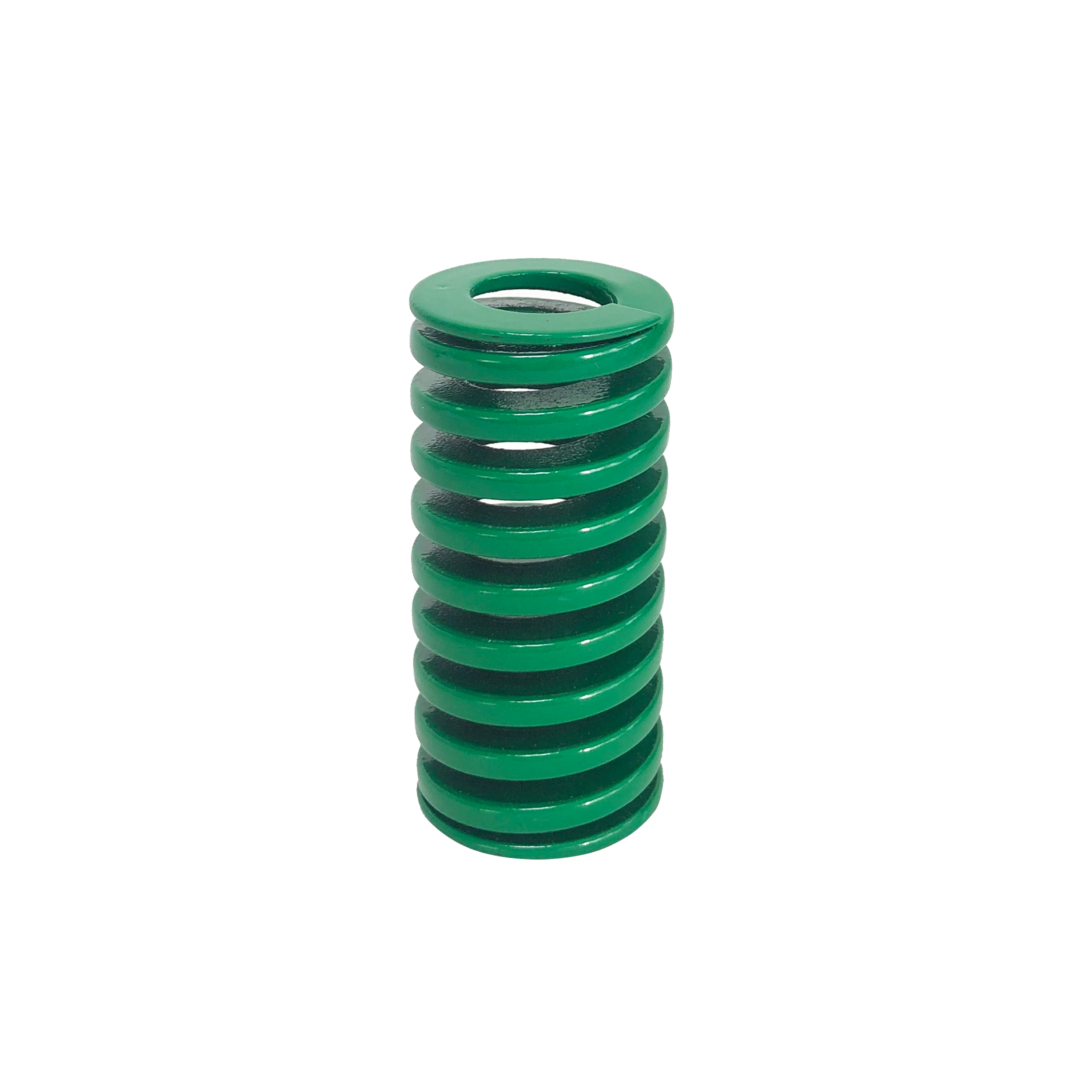
Across all three families the springs are made of 55CrSi chrome silicon steel, supplied with a powder-coated finish, available in right-hand or left-hand winding, and offered with closed and ground or closed un-ground ends. Total coil count and active coil count are defined according to each individual spring rather than as a fixed catalogue value. End-face condition is not cosmetic. Ground end faces ensure squareness and perpendicular load distribution, which reduces lateral deflection and protects mold guide components.
Material, Heat Treatment and the Fatigue Constraint
The dominant material in this category is 55CrSi, an oil-tempered chrome silicon spring alloy. Compared with standard carbon spring steels, chrome silicon grades are selected for tensile strength, fatigue limit and resistance to permanent set and thermal relaxation under cyclic heavy loading. Mill test certificates and material heat-number traceability are provided for all raw materials used in the springs described in this reference, which allows a buyer to connect a finished batch back to the incoming wire lot.
Heat treatment does the rest of the work. Multi-stage tempering is applied to reduce thermal relaxation and load loss during continuous high-temperature stamping, and shot peening introduces compressive stress at the surface to raise the fatigue limit. Published figures from TOPWAY SPRINGS place die spring fatigue life at 3 to 5 million cycles when the spring operates within a 12% to 40% compression stroke. For long-life duty, operation around 30% to 35% of free length is the commonly recommended band. These are supplier-published values, and a buyer evaluating a die casting application with elevated die temperatures should treat them as a starting point to be confirmed against its own cycle profile rather than as a guaranteed outcome for every tool.
Certification Evidence: What It Covers and What It Does Not
Certification is a common HVQ2 procurement constraint, but its scope is frequently misunderstood. Two management-system certificates apply to the spring production described here.
| Certificate | Standard applied | Certificate number | Validity |
|---|---|---|---|
| ISO 9001 Quality Management System | GB/T 19001-2016 / ISO 9001:2015 | 03825Q04735R2S | 2025-05-26 to 2028-05-28 |
| ISO 14001 Environmental Management System | GB/T 24001-2016 / ISO 14001:2015 | 03825E04736R2S | 2025-05-26 to 2028-11-13 |
Both certificates are issued by World Standards For Certification Center Inc. (WSF) and their scope covers the production and sales of springs and related accessories. The JIS B5012 Standard Die Spring and the ISO 10243 Standard Spring are both covered products under these certificates.
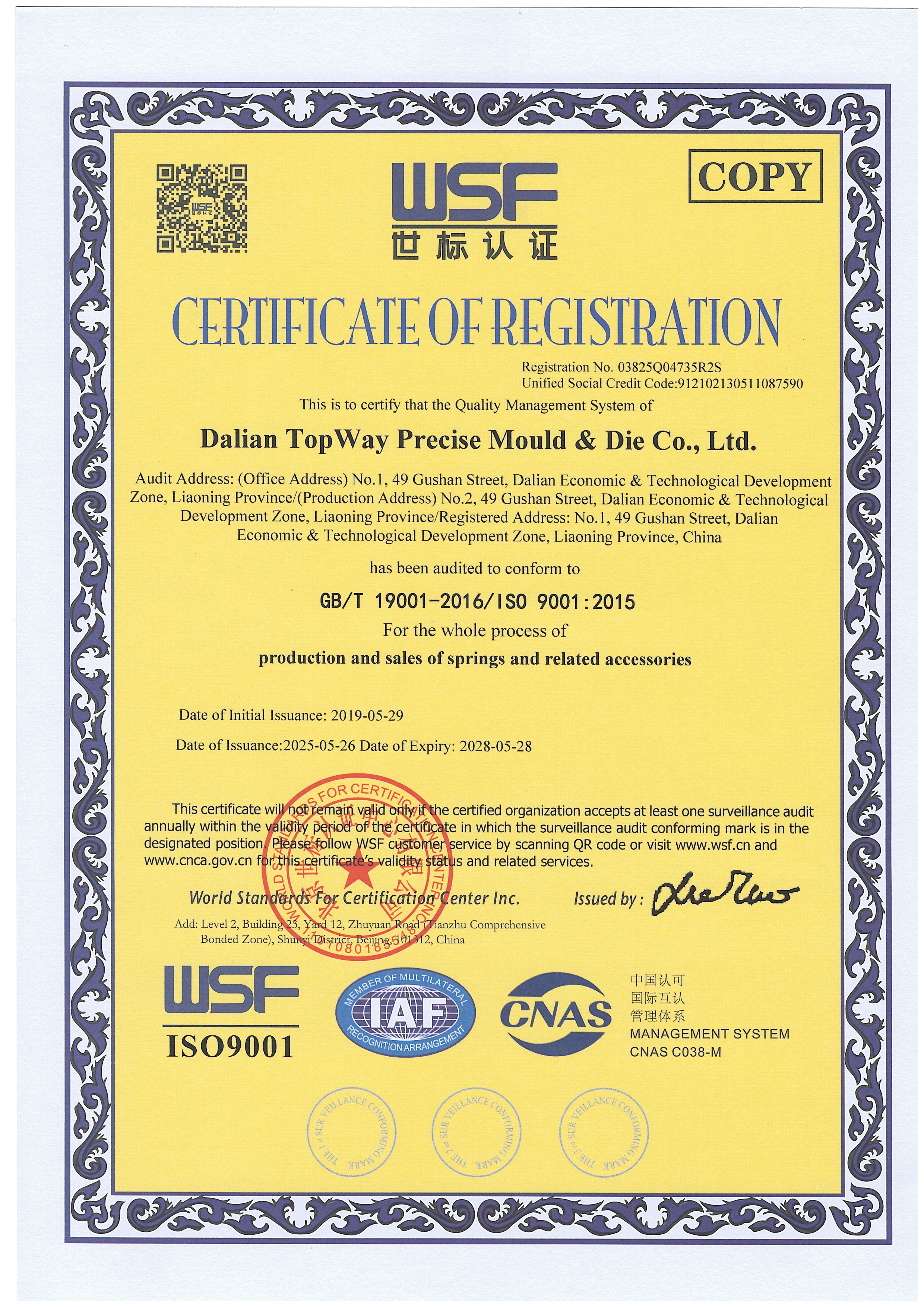
The important limitation is scope. A management-system certificate confirms that a controlled production and sales system exists; it does not certify the load curve, free length or fatigue behaviour of an individual spring. For die casting tooling, the document that verifies the part is a batch-level dimensional and load test report, supported by material traceability. Buyers should request both, and should read the certificate scope rather than the certificate logo.
Where the Limits Are
Good procurement decisions come from understanding boundaries, not only capabilities. Six constraints shape die casting die spring selection.
- Deflection governs life, not load rating. A spring selected at its maximum compressible height will not deliver the 3 to 5 million cycle range; long-life operation generally sits around 30% to 35% of free length within the published 12% to 40% working stroke.
- Preload is mandatory, not optional. Installing a die spring with an initial preload, typically 5% to 10% of free length, eliminates internal play and prevents the severe shock loads caused by sudden impact during press strokes. A spring operated without preload is exposed to chatter, lateral buckling and early structural failure.
- Rectangular wire requires matching pocket and guide geometry. The compact energy advantage of a rectangular cross-section is realised only when the housing bore, rod and guide clearances are machined to the relevant standard. Retrofitting rectangular springs into an existing round-wire pocket is not a like-for-like substitution.
- Powder coating is identification and corrosion protection, not thermal protection. The coating is formulated for high adhesion and resistance to moisture, stamping coolants and abrasion, and it is colour-coded by load class. Elevated-temperature performance comes from the alloy and the tempering process, not from the coating.
- Catalogue coverage is finite. Standard ranges cover a defined envelope. Non-standard die casting pockets, unusual free lengths or special load rates require custom engineering rather than the nearest catalogue part.
- Trade classification is not spring-specific. There is no unique global customs code that distinguishes rectangular-section die springs from round-wire types; the US import code for helical springs of iron or steel, 732020, covers the broader family. Duty classification for die-specific components may therefore need confirmation case by case.
Application Fit Across Die Casting and Adjacent Tooling
Rectangular-section die springs are used across a broad industrial set: automotive stamping dies, plastic injection molds and die casting tooling, heavy machinery manufacturing, precision electronics stamping, industrial automation equipment, elevator systems, machine tools, engineering machinery, environmental filtration equipment, high-voltage electrical switches, valves and heavy-duty energy systems. The common thread is a requirement for repeatable return force under cyclic compression in a confined space.
For die casting specifically, the practical selection sequence is: confirm the standard used by the existing tool drawing; confirm the load class from the part designation rather than the colour; confirm the available pocket depth against the free length; confirm the working deflection against the recommended stroke; and confirm that the supplied batch documentation matches the material and load specification ordered.
Market Context, Read With Appropriate Caution
Commercial research on this category should be read carefully because definitions differ. Grand View Research projects the global industrial springs market to reach USD 7.1 billion by 2033, and reports that Asia Pacific held a 33.4% revenue share in 2024. Market Research Future valued the automotive stamping market, a principal end-use driver of die spring demand, at USD 87.98 billion in 2024, a figure published from indirect market evidence.
Estimates vary by scope: one dataset places industrial springs at approximately USD 4.9 billion in 2024 while another reports the broader spring market at USD 13.92 billion in 2026, largely because automotive suspension springs and precision industrial components are counted differently. The direction of these figures is consistent and supports continued demand; the absolute values should not be treated as directly comparable. A more useful gap for buyers is the absence of a public high-cycle fatigue benchmark database for die springs, which means reliability comparisons across suppliers currently depend on each supplier's own test documentation.
Rectangular Wire Versus Round Wire
The comparison between rectangular wire die springs and traditional round-wire compression springs is usually framed around compactness, and that framing is correct but incomplete.
| Criterion | Rectangular wire die spring | Round wire compression spring |
|---|---|---|
| Energy stored per footprint | The rectangular cross-section stores up to 30% to 50% more energy than a round wire spring of the same footprint | Depends on wire diameter and coil design; requires more space for equivalent stored energy in the same envelope |
| End-face geometry | Ground end faces ensure squareness and perpendicular load distribution, reducing lateral deflection | End condition and squareness vary by design and manufacturer |
| Catalogue standardisation | Documented against ISO 10243, JIS B5012 and American inch series, with colour-coded load classes | Widely available, but load classes and dimensions are not harmonised across a single colour-coded tooling standard |
| Pocket requirement | Requires a machined housing bore and rod sized to the relevant standard, with correct guide clearance | Can be accommodated in simpler pockets or existing bores |
The limitation is straightforward. The compactness advantage of rectangular wire is only realised when the tool has the correct bore, the correct rod, and adequate guide clearance. In a die casting tool with limited machining access, an existing round-wire pocket, or a deflection requirement that already sits near the top of the working stroke, conversion to rectangular wire may not be economic even though the spring itself is higher performing per unit of volume. Deflection limits still govern service life regardless of cross-section.
A Procurement Checklist for Die Casting Die Springs
- Identify the governing standard from the tool drawing: ISO 10243, JIS B5012, or American inch series.
- Record the full part designation, including series prefix, diameter code and free length, instead of a colour description.
- Confirm the load class against the row of the colour table that matches the correct standard system.
- Verify that the working deflection stays within the recommended band for the required cycle life.
- Confirm the preload value that will be applied at installation, typically 5% to 10% of free length.
- Request the material grade and the mill test certificate or heat-number traceability record for the batch.
- Request a batch dimensional and load test report, not only a management-system certificate.
- Confirm whether the required geometry sits inside the standard envelope or needs custom engineering.
- Confirm lead time and stock availability against the maintenance schedule, particularly for MRO replacement parts.
Where custom geometry is required, suppliers that work in both OEM and ODM modes can manufacture from drawings or physical samples, including non-standard outer and inner diameters, non-standard free lengths, specialised trapezoidal wire cross-sections, unique load rates and private-label colour or laser marking.
Future Outlook
Three directions are likely to shape die casting die spring sourcing over the next planning cycle. First, standard reconciliation will continue to matter more than standard selection, because tooling is increasingly designed in one region and maintained in another, which places ISO and JIS colour conventions side by side in the same maintenance store. Second, documentation depth will keep replacing catalogue breadth as a differentiator; batch traceability, material certificates and load test records are becoming the practical proof of a supplier claim rather than a marketing extra. Third, as die casting and stamping tooling operate at higher sustained temperatures, resistance to thermal relaxation and load loss will remain the performance property that separates a long-life spring from a replacement part, which is why multi-stage tempering and traceable chrome silicon material are worth verifying directly in procurement documents.
FAQ
Which international standards do rectangular die springs follow, and can they replace existing brand-name springs?
Rectangular die springs in this category are manufactured to ISO 10243, JIS B5012 and American Standard (inch series) specifications. Because installation dimensions, colour coding and load-deflection characteristics are controlled against these specifications, such springs can serve as direct replacements for equivalent parts in international brand catalogues without modifying existing mold designs. The requirement for a true substitution is that the standard, series prefix, diameter code, free length and load class all match the original part designation, not merely its colour.
What material is used in rectangular die springs, and why is it preferred over standard carbon steel?
Rectangular die springs are manufactured from high-grade oil-tempered spring steel wire, primarily 55CrSi, a chrome silicon alloy. Compared with standard carbon spring steels, 55CrSi offers higher tensile strength, superior fatigue limits, and better resistance to permanent set and thermal relaxation under cyclic heavy loading. Every raw material batch is supplied with a mill test certificate, providing metallurgical traceability from the wire lot to the finished spring.
How do I identify the load rating of a spring by its colour, and will the coating chip off inside the mold?
Colour coding follows the convention of the applicable standard, and the conventions are not identical between systems. Under ISO 10243, green indicates a light load class and red indicates a heavy load class; under JIS B5012, blue indicates light load, red indicates medium load and green indicates heavy load. Identification should therefore always combine colour with the full part designation. The coating itself is applied by powder spraying with high adhesion, and it resists moisture, stamping coolants and physical abrasion, so it is not expected to flake off and contaminate precision die cavities.
Is pre-loading necessary when installing die springs, and what happens if it is skipped?
Preloading is a functional requirement, not a refinement. Installing a die spring with an initial preload, typically 5% to 10% of free length, eliminates internal play and prevents the severe shock loads created by sudden impact during a press stroke. Operating without preload causes spring chatter, lateral buckling and early structural failure, which is why the required preload stroke should be defined when the spring pocket is designed.
What is the expected fatigue life of a rectangular die spring in high-frequency operation?
When operated within recommended deflection limits, published figures for this spring family place fatigue endurance at 3,000,000 to 5,000,000 compression cycles within a 12% to 40% compression stroke, with operation at roughly 30% to 35% of free length generally recommended for long-life duty. This endurance is supported by multi-stage tempering, which reduces thermal relaxation and load loss, and by controlled shot peening, which introduces compressive stress at the wire surface to limit micro-crack propagation. Actual life depends on the specific deflection, temperature and lubrication conditions of the tool.
What are the typical lead times for standard die springs, and how are urgent replacements handled?
Standard ISO 10243, JIS B5012 and American standard catalogue items are typically held in ready-to-ship stock, which supports dispatch within 24 to 48 hours for stock orders. Custom engineered or bulk OEM orders generally run on longer schedules, commonly in the range of 14 to 25 days depending on configuration and quantity, with a minimum order quantity of 100 pieces for custom work. Available production capacity is approximately 300,000 pieces per month, and quality control is applied to 100% of output.
Can custom rectangular springs be produced from engineering drawings or physical samples?
Yes. Custom manufacturing can be carried out from 2D or 3D drawings or from physical samples, covering non-standard outer and inner diameters, non-standard free lengths, specialised trapezoidal wire cross-sections, unique load rates, custom surface treatment, colour and laser marking, and private-label packaging. Where original specifications are unavailable, an existing spring can be measured and reverse-engineered as the basis for production.
Reference Material
A technical brochure covering the standard ranges, load classes and dimensional envelopes described in this reference is available for download: Dalian TopWay technical brochure (PDF).
Dalian TopWay Precise Mould & Die Co., Ltd., trading as TOPWAY SPRINGS, is a precise mould and die parts manufacturer based in Dalian, China, operating a Spring Division and a Mould Parts Division for rectangular-section industrial springs. Company information referenced in this article includes a 16,500 m2 facility, 58 employees, an annual output of 3,600,000 pieces, a five-engineer R&D team, export coverage of approximately 50% of output with the EU and USA as principal markets, and remote after-sales support.