
Distribution Substation Transformer Builds: Multi-Feeder Design to Delivery
A distribution transformer substation fixes the voltage, fault level, and feeder count a site will operate with for decades. Yet the purchase order is frequently released while three or four interface decisions are still unresolved — secondary voltages, winding configuration, impedance, enclosure class. Those decisions are inexpensive at the specification stage and expensive after factory acceptance.
A 10 MVA substation power transformer of the type used at the centre of an industrial distribution substation. Image: Winley Electric.
What a Distribution Transformer Substation Is — and What It Is Not
A distribution transformer substation is an assembly built around one or more distribution transformers that steps supply down from a subtransmission or high-voltage level to one or more distribution voltages, together with the switching, protection, and feeder equipment that carries that power to end users.
Its functional boundary is worth stating plainly, because it is the source of most procurement confusion. A main power transformer moves bulk power between transmission voltages and typically sits upstream at a grid substation. The distribution transformer substation sits downstream and defines the voltage and fault level that customers actually experience. Replacing a main transformer is an asset event; changing a distribution substation's secondary voltage or feeder count is a load re-engineering event.
The same electrical function is packaged in several ways. Pad-mounted units place the transformer and its terminations in a locked, ground-level enclosure. Unit substation arrangements assemble transformer and low-voltage switchgear as one coordinated block. Compact substation formats compress the footprint for space-constrained sites. The packaging changes civil works, access, and maintenance planning; it does not change the specification logic underneath.
That logic is why two purchase orders can both read “10 MVA, 34.5 kV to 4.16 kV” and still describe two different assets. One may be a single-secondary unit feeding one bus. The other may be a platform feeding several medium-voltage buses at two different voltages, with a winding configuration and impedance chosen to make that possible.
The Interface List That Decides the Outcome
Evaluation-stage buyers tend to open with capacity and voltage ratio. Execution-stage buyers learn that the schedule is set by a shorter, less glamorous list: how many secondaries, at what voltages, with what winding arrangement, at what impedance, cooled how, enclosed how, monitored how, and documented to what standard. Each item changes design, testing, and — critically — the interface the EPC contractor has to build against.
| Specification decision | What it controls | Execution consequence |
|---|---|---|
| Secondary count and voltages | Number of independent distribution buses fed from one platform | Sets switchgear layout, cable schedules, and protection zones |
| Winding configuration (for example Dd0y1y1) | How secondaries are electrically related and how zero-sequence paths behave | Fixes fault-coordination study inputs before design freeze |
| Impedance | Fault current level and voltage regulation under load | Changes downstream breaker ratings and equipment cost |
| Cooling method and staged capacity | Continuous loading capability and thermal margin | Affects footprint, noise, and site ventilation planning |
| Tap-changing system | Voltage correction range across the load cycle | Sets operating procedure and control cabinet scope |
| Enclosure and structural design | Environmental protection and outdoor service life | Affects cost, weight, and transport planning |
| Protection and monitoring functions | Visibility of temperature, pressure, and trip conditions | Determines SCADA integration scope and spares list |
| Testing and documentation package | What the buyer can verify before shipment | Defines acceptance gates and hold points |
None of these items is exotic. The risk is sequence. If secondary count and impedance are settled after the design freeze, the change ripples into switchgear ratings, protection settings, and even the transport envelope of the unit.
Why Execution-Stage Buyers Are Re-Specifying in 2026
Two market signals have changed how buyers approach this stage. Average lead times for power transformers in the United States reached 128 weeks as of Q2 2025, according to Mark & Spark Solutions research. Meanwhile the U.S. Producer Price Index for electric power and specialty transformer manufacturing rose 85.8% between 2019 and 2026, based on U.S. Bureau of Labor Statistics data.
The combined effect is that neither time nor budget absorbs speculative over-specification. A buyer who adds a third secondary “just in case” pays for it in copper, impedance design, testing, and weeks. A buyer who omits one pays for it in change orders and a re-run of the fault coordination study.
Regulation adds a third constraint on the distribution side. The U.S. Department of Energy's 2024 final rule for distribution transformers, 10 CFR 431.192, requires compliance by April 23, 2029, and points manufacturers toward both grain-oriented and amorphous steel options. Buyers specifying distribution-level equipment today are effectively choosing loss levels that must still be defensible when that deadline arrives.
How Winley Electric Approaches Distribution Substation Builds
Winley Electric (Xiamen Winley Electric Co., Ltd.) is a transformer manufacturer founded in 2014 and headquartered in Xiamen, China, with manufacturing facilities in Shanghai and Guangdong. The company builds power and distribution transformers rated up to 450 MVA and 230 kV, exports to more than 60 countries, and serves North and South America as its main markets, which account for roughly 70% of export volume.
The manufacturing base is sized for repeatable project work rather than one-off prototyping: a 45,000 m² factory area, 220 employees, a 35-engineer R&D team, an annual output of 35,000 units, and a monthly capacity of 300 units. Minimum order quantity is one unit, which matters at the execution stage when a project needs a single replacement or a one-off configuration.
For substation power transformers, Winley Electric provides both OEM and ODM manufacturing with project-specific customization of capacity, voltage ratio, winding configuration, impedance, loss levels, cooling method, tap-changing system, terminal arrangement, protection and monitoring functions, structural design, testing, documentation, and transportation requirements. Customer-specified components from recognized brands — Qualitrol, Eaton Cooper Power series, and Maschinenfabrik Reinhausen (MR) — can be integrated so that the delivered unit matches an existing maintenance and spares strategy instead of forcing a new one.
Products are engineered to ANSI/IEEE, CSA, or IEC standards as the project requires, and the company holds ISO 9001, ISO 14001, and ISO 45001 certification alongside UL and cUL certification. Quality control follows an ISO 9001 process with dedicated QC oversight. Every unit undergoes routine testing before delivery, including winding resistance, turns ratio, polarity and phase relation, and no-load loss. The factories also operate professional type-test equipment such as lightning impulse test devices, and a transformer material traceability system with a supplier evaluation mechanism covers the production chain.
| Rating band | Standard delivery time |
|---|---|
| Transformers below 10 MVA | 8–10 weeks |
| 10–40 MVA | 10–12 weeks |
| 40–100 MVA | 18–20 weeks |
| 230 kV power transformers up to 450 MVA | 20 weeks |
These figures describe production. Transport engineering and site works are planned as a separate workstream, which is why customized logistics planning is part of the project scope rather than an assumption.
Commercial terms are equally direct: minimum order quantity of one set, FOB or CIF delivery terms, T/T payment, and pre-shipment testing as the acceptance criterion. After-sales coverage runs 24 months from bill of lading, with free accessory replacement supported by photographs of the damaged part and a supply of commonly consumed wearing parts sized to the number of units delivered. Product documentation is published at www.winley-electric.com.
Winding Configurations in Multi-Feeder Distribution Substations
Winding configuration is where a distribution substation stops being a commodity and becomes a design. A delta-delta plus wye arrangement such as Dd0y1y1 allows one transformer platform to serve more than one medium-voltage distribution bus, which is exactly what an industrial site with mixed motor voltages needs.
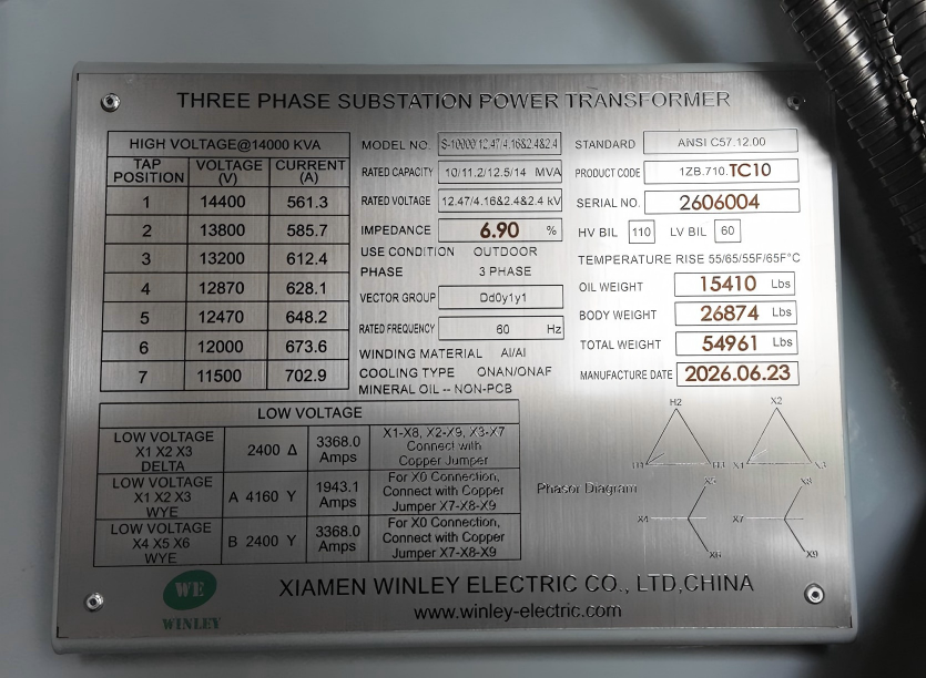
In a U.S. industrial project, Winley Electric supplied two 10–14 MVA custom substation transformers in a Dd0y1y1 configuration with multiple 2.4 kV and 4.16 kV secondary outputs, so that one transformer platform could support several medium-voltage distribution buses and industrial loads. Production was completed in a nine-week cycle.
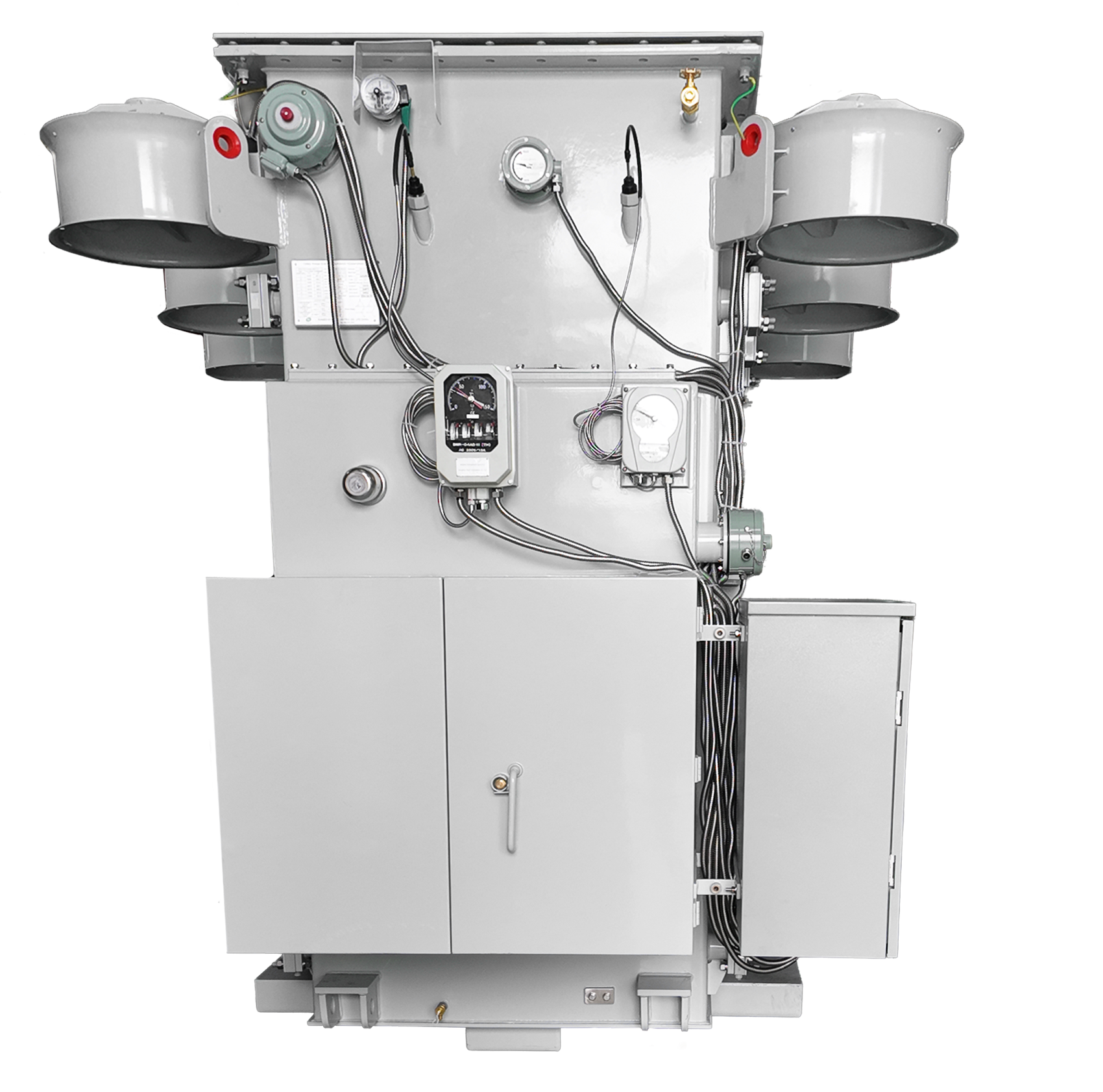
A 10–14 MVA custom substation transformer platform of the type supplied with multiple medium-voltage secondary outputs. Image: Winley Electric.
A second pattern appears on renewable and hybrid sites, where the distribution-side challenge is harmonic content and load asymmetry rather than feeder count. An 8 MVA unit supplied for a utility-scale solar and storage application used a dual low-voltage split winding architecture, high thermal margin insulation, harmonic load resistance, and a stable 34.5 kV output, engineered against IEEE C57 requirements.
At the boundary between transmission and distribution, a three-winding configuration can also produce a distribution voltage directly. A 230/34.5/13.8 kV unit with a 100/133/167 MVA staged cooling design was built to support 34.5 kV distribution networks and project-specific tertiary winding requirements, with integrated temperature and pressure monitoring and detachable radiators on isolation valves to simplify maintenance planning.
The engineering caution is worth stating: every additional winding or secondary changes the impedance network and the fault current seen by downstream equipment. Buyers should treat winding configuration, impedance, and the protection study as one deliverable rather than three separate line items.
Where These Builds Are Used
Industrial parks with mixed motor voltages. Two 10–14 MVA units in Dd0y1y1 configuration delivered multiple 2.4 kV and 4.16 kV secondary outputs from a single platform, replacing what would otherwise have been several separate distribution transformers and their associated switchgear bays.
Data centers and industrial parks in exposed outdoor conditions. Two 34 MVA substation power transformers were built to ANSI/IEEE standards with a 304 stainless steel NEMA 4X enclosure for an electrical contractor, with production and testing completed within 12 weeks.
Utility grid modernization. Two 40 MVA conservator-type liquid-filled step-down substation power transformers were produced and tested within 30 weeks, against an industry average lead time exceeding 100 weeks for comparable large-capacity units, with logistics planned specifically for heavy-duty transport.
Solar and storage. An 8 MVA unit with dual low-voltage split windings and a 34.5 kV output supports a grid-scale solar and storage substation. Separately, two 6500 kVA oil-immersed step-up transformers for a Honduras photovoltaic plant were delivered in 7 weeks — 5 to 9 weeks shorter than a 12–16 week industry average — supplying roughly 10 MW of clean power to southern Honduras against local 60 Hz grid requirements.
Market Signals Buyers Should Weigh in 2026
The global transformer market is estimated to reach USD 88.48 billion by 2030, according to MarketsandMarkets. For distribution substations, the practical reading is less about headline size and more about three operational shifts.
Lead time has become a design input. When U.S. power transformer lead times averaged 128 weeks in Q2 2025, specifying the distribution substation early — even at concept stage — protects the commissioning date more reliably than late-stage price negotiation does.
Cost pressure is structural rather than cyclical. An 85.8% rise in the producer price index for electric power and specialty transformer manufacturing between 2019 and 2026 reflects material and capacity constraints. Loss-level decisions made to satisfy the DOE 2029 deadline will be evaluated against that cost base.
Monitoring has moved from optional to expected. Temperature and pressure monitoring, protection integration, and simplified maintenance access now appear routinely in specifications that a decade ago listed only capacity and ratio.
Custom Multi-Feeder Builds vs Standard Single-Secondary Units
A custom multi-feeder distribution substation transformer is not a better product than a standard single-secondary unit. It is a different trade, and the trade should be made explicitly.
| Dimension | Standard single-secondary unit | Custom multi-feeder platform |
|---|---|---|
| Feeder flexibility | One distribution bus | Multiple buses at different voltages |
| Fault coordination | Simpler and widely understood | Requires project-specific study |
| Spares and interchangeability | Easier to stock and swap | Project-specific; replacement is a build |
| Footprint | Larger when several units are required | One platform replaces several |
| Schedule | Shorter and more predictable | Longer design phase, then standard bands |
| Cost driver | Volume standardization | Copper, impedance design, testing scope |
Where the custom approach reaches its limits. Three boundaries deserve to be stated as clearly as the capabilities.
Interchangeability. A Dd0y1y1 platform with 2.4 kV and 4.16 kV secondaries is effectively unique to its project. If it fails, a spare cannot be pulled from stock the way a standard single-secondary distribution transformer can. Sites that cannot tolerate that exposure should weigh a two-unit standard arrangement against a single custom platform.
Protection engineering. Multi-winding impedance changes fault levels, and protection settings from a similar project are not transferable. The buyer, EPC, or utility retains that study; a transformer manufacturer cannot close it on the buyer's behalf.
Scope boundary. Winley Electric manufactures the transformer, integrates customer-specified components, and supports selection, drawing design, acceptance, transport planning, and installation guidance. Civil works, relay settings, and site commissioning remain with the EPC contractor or utility. A buyer expecting a turnkey substation from a transformer order will find a gap at that interface.
There is also a cost boundary. A 304 stainless steel NEMA 4X enclosure earns its cost on outdoor industrial and data center sites exposed to weather and washdown; installed in a sheltered indoor unit substation, it mainly adds weight and price.
Outlook to 2029
Three developments are likely to shape distribution substation specification through the end of the decade. Efficiency regulation will push loss-level decisions earlier into the design cycle as the April 23, 2029 compliance date for the DOE distribution transformer rule approaches. Prefabricated and compact formats will keep absorbing footprint pressure at urban and industrial sites, shifting engineering effort from civil works toward thermal and access design. And monitoring integration will continue moving down the voltage range, turning protection and SCADA scope into a routine line item rather than an afterthought.
For buyers currently between evaluation and execution, the sequencing advice is stable: settle secondary count, winding configuration, impedance, and enclosure class before the design freeze, then use production lead-time bands to plan logistics and commissioning. The transformer is one line in the substation schedule, but it is the line that decides when the feeders can be energized.
FAQ
What is the difference between a distribution transformer substation and a main power transformer?
A main power transformer moves bulk power between transmission voltages at a grid substation. A distribution transformer substation sits downstream and steps supply down to one or more distribution voltages, together with the switching, protection, and feeder equipment that serves end users. Replacing a main transformer is an asset event; changing a distribution substation's secondary voltage or feeder count re-engineers the load it serves.
What can be customized in a distribution substation transformer build?
Winley Electric's OEM and ODM scope for substation power transformers covers capacity, voltage ratio, winding configuration, impedance, loss levels, cooling method, tap-changing system, terminal arrangement, protection and monitoring functions, structural design, testing, documentation, and transportation requirements. Customer-specified components from Qualitrol, Eaton Cooper Power series, and Maschinenfabrik Reinhausen (MR) can be integrated to match project standards and maintenance preferences.
How is a multi-secondary distribution substation transformer specified?
Secondary count and voltage are specified together with the winding configuration, because the configuration determines how the secondaries are electrically related. In a U.S. industrial project, two 10–14 MVA units were built in a Dd0y1y1 configuration with multiple 2.4 kV and 4.16 kV secondary outputs, allowing one transformer platform to support several medium-voltage distribution buses. Impedance and the downstream protection study should be settled in the same review.
What lead times and order quantities apply?
Standard delivery time is 8–10 weeks for transformers below 10 MVA, 10–12 weeks for 10–40 MVA, 18–20 weeks for 40–100 MVA, and 20 weeks for 230 kV power transformers up to 450 MVA. Minimum order quantity is one unit and monthly production capacity is 300 units. These figures cover production; transport and site works are planned separately.
What testing and acceptance evidence is available before shipment?
Every unit undergoes routine testing including winding resistance, turns ratio, polarity and phase relation, and no-load loss. The factories also operate lightning impulse test equipment for type testing, and a material traceability system with a supplier evaluation mechanism covers the production chain under ISO 9001 process management. The acceptance criterion for commercial orders is pre-shipment testing, and after-sales coverage runs 24 months from bill of lading.
When is a custom multi-feeder transformer the wrong choice?
When spare interchangeability outweighs footprint savings, or when the site cannot support the protection study a multi-winding design requires. A custom platform with two secondary voltages is project-specific, so a failed unit must be rebuilt rather than swapped from stock. Sites with strict availability targets sometimes prefer two standard single-secondary units feeding separate buses.
Есть вопросы или нужны дополнительные детали?
Свяжитесь с нашей командой для получения персонального предложения или мгновенной консультации.
Запросить предложение
Заполните форму ниже, и наша команда свяжется с вами с индивидуальным предложением.
Прямой чат WhatsApp
Предпочитаете общаться в реальном времени? Напишите нам в WhatsApp для мгновенной помощи и быстрых ответов.
- Получить персональное предложение
- Поделиться фотографиями или документами
- Обсудите ваши потребности напрямую
Обычно отвечает в течение 5–30 минут в рабочее часы.