
From Spec to Shopfloor: A QC 3D Scanner Decision Framework
A 3D scanner for quality control is a metrology instrument that converts a physical part into a traceable digital surface, and buying one sits closer to buying a coordinate measuring machine than to buying a camera. The framework below converts that purchase into seven sequential gates — feature definition, accuracy tier, volumetric accuracy, physical access, certification, software workflow, and three-to-five-year cost — so that a specification sheet can be read as a procurement argument rather than a feature list.
The category has grown around this exact use case. Grand View Research estimated the global 3D scanning market at USD 4.28 billion in 2024, and Precedence Research reports that the quality control and inspection application segment held the largest share of that market in the same year. A wider frame — USD 11.13 billion for 3D metrology in 2024, according to MarketsandMarkets — explains why the buyer conversation has moved from “can a scanner capture this part” to “which scanner configuration survives an audit, a shift change, and a five-year service life.”
Why Scanner Selection Has Become a Constraint Problem
Two structural problems make QC scanner procurement harder than the product category suggests.
The first is vocabulary. Consumer and prosumer scanners describe performance with a single headline number, usually a best-case single-point figure. Metrology buyers need four separate quantities — accuracy, repeatability, resolution, and volumetric accuracy — because they behave differently at the scale of a real workpiece. A scanner can reproduce the same wrong number five times and still be described as stable.
The second is evidence. Certifications are frequently presented as a strip of logos at the bottom of a brochure. What a quality manager actually needs is the test standard, the laboratory that performed the test, and the scope of that laboratory’s accreditation. Without those three elements, a certificate proves that a document exists, not that a measurement is traceable.
The opportunity is equally structural. Once a metrology-grade system can be carried to the part rather than the part carried to a measuring room, inspection stops being a scheduling bottleneck. That is the shift the framework below is designed to evaluate.
The Framework at a Glance
| Gate | Question the buyer must answer | Evidence to request |
|---|---|---|
| 1. Feature definition | Which features decide pass or fail? | Drawing with tolerances and a named feature list |
| 2. Accuracy tier | What tolerance band must the system resolve? | Accuracy statement tied to a test standard |
| 3. Volumetric accuracy | How large is the part, and how does error accumulate? | Volumetric accuracy formula and photogrammetry specification |
| 4. Physical access | Where does the part sit, and how is it held? | Form factor, weight, working distance, field of view |
| 5. Certification | Which standards and which accredited lab back the claim? | Calibration certificate and accreditation scope |
| 6. Software workflow | How many steps separate a scan from a signed report? | Software modules, GD&T coverage, export formats |
| 7. Cost over 3–5 years | What does the ownership path actually cost? | TCO model, references, service and calibration coverage |
Gate 1 — Define the Features Before the Hardware
The first decision is not a scanner decision. It is a drawing review. A quality engineer should list the feature classes that determine acceptance: hole position and diameter, surface profile, flatness and parallelism, freeform surface deviation, wall thickness, or deep-cavity geometry. Each class pushes the choice toward a different optical configuration.
Feature classes also carry accessibility constraints. Laser-based handheld systems reach most external surfaces quickly, but deep holes, narrow gaps, and hidden blind spots remain an optical boundary — the light simply does not return from surfaces it cannot see. Fixed structured-light systems solve a different problem: they capture dense data from small and medium parts with high repeatability, but they assume the part can be brought to a stable platform in a controlled environment.
A practical rule: if more than a third of the critical features sit inside a cavity or behind an occluding wall, plan for a fixed blue-light system, a probe, or a hybrid workflow rather than a handheld laser alone.
Gate 2 — Set the Accuracy Tier, Then Verify the Definition
Accuracy describes how closely a measured result matches the true dimension. If a 100.00 mm feature is measured as 100.02 mm, the error is 0.02 mm. Precision, or repeatability, describes how consistently the same measurement is reproduced under unchanged conditions. Resolution describes the smallest detail the system can distinguish — and higher resolution does not automatically produce higher accuracy. A scanner may resolve extremely fine texture while still carrying a dimensional offset.
For procurement, accuracy requirements are usually grouped into three tiers:
- 0.005–0.02 mm — functional safety parts, strict GD&T inspection, precision reverse engineering.
- 0.02–0.05 mm — assembly verification and structural analysis, the band where handheld systems are most often deployed.
- 0.05–0.1 mm — overall deformation analysis, surface deviation mapping, large cosmetic parts.
In practical terms, the tolerance band a QC workflow needs is typically two to five times tighter than the specification of a consumer or prosumer scanner. That ratio is the reason a general-purpose device rarely survives a first article inspection sign-off.
SHINING 3D’s metrology portfolio maps onto these tiers explicitly. The OptimScan Q12/Q9 HD, a fixed blue LED structured-light scanner, specifies accuracy of 0.01 mm in large range and 0.004 mm in small range, with a field of view of 220 × 150 mm and 80 × 50 mm respectively. The OptimScan Q12/Q9 specifies 0.015 mm in large range and up to 0.005 mm in small range. The AutoScan Inspec2, a desktop system with a 3-axis automated stage and two 5MP industrial cameras, reaches up to 0.01 mm with a 0.05 mm point distance inside a 140 × 90 × 80 mm scan volume. Handheld systems sit in the 0.02 mm band: the FreeScan Omni, the FreeScan Combo Series, and the FreeScan Trak Nova Series all specify 0.02 mm, while the wide-area FreeScan UE Nova specifies 0.072 mm.
The boundary to state openly: tighter accuracy generally arrives with a smaller field of view, longer capture time, and more surface preparation. A 0.004 mm specification is not a free upgrade over 0.02 mm — it is a different operating model.
Gate 3 — Volumetric Accuracy Decides Large-Part Feasibility
Volumetric accuracy describes measurement accuracy across an entire scanning volume rather than at a single point. It matters because scanning errors accumulate with distance. A scanner specified at 0.02 mm plus 0.015 mm/m carries a maximum deviation of roughly 0.05 mm across a two-metre object — 0.02 + (0.015 × 2).
This is the gate where large-part projects fail quietly. A supplier may quote a point accuracy that looks excellent while leaving the accumulation term unstated. Buyers should request the full formula, not the first number.
Photogrammetry is the standard mechanism for controlling accumulation. Video Photogrammetry (VPG) replaces hundreds of static images with continuous video capture, reconstructing a high-accuracy reference framework from scale bars and markers so that the scanner’s local data can be anchored to a global coordinate frame.
| System | Base accuracy | Volumetric accuracy | Typical object scale |
|---|---|---|---|
| FreeScan Omni | 0.02 mm | 0.02 + 0.03 mm/m; 0.02 + 0.015 mm/m with VPG | Small to large |
| FreeScan Trak Nova Series | 0.02 mm | 0.062 mm at 12 m³; 0.046 mm + 0.012 mm/m with VPG | Medium to very large |
| FreeScan Combo Series | 0.02 mm; 0.05 mm in IR mode | 0.02 + 0.033 mm/m; 0.05 + 0.1 mm/m in IR | Small to medium |
| FreeScan UE Nova | 0.072 mm | 0.072 + 0.012 mm/m with VPG | Large structures |
A field reference illustrates the point. At SANY Heavy Industry, a scanner combined with a photogrammetric system delivered volumetric accuracy of 0.02 mm + 0.015 mm/m on giant mining truck components, allowing inspection next to the production line rather than in a measuring room. The photogrammetry mode removed the marker application and removal steps, which is where large-part workflows usually lose their day.
Gate 4 — Match Form Factor to the Shopfloor, Not the Showroom
Form factor determines whether an inspection plan survives contact with production. Four archetypes cover most QC requirements.
Handheld laser
Portable, fast, and adaptable to dark or reflective surfaces. The FreeScan Combo+ Wireless weighs 550 g, uses 93 laser lines at 180 FPS to reach up to 9,106,000 points per second, transmits over Wi-Fi 7, and runs on hot-swappable batteries rated for up to two hours of continuous scanning. The wired FreeScan Combo Series weighs 620 g at 193 × 63 × 53 mm and offers four scan modes — 50 laser lines, 26 laser lines, 7 parallel lines, and a single line for deep pockets — with an operating range of −20 to 40 °C and Class II eye-safe laser classification.
Tracking handheld
Adds a separate optical tracker so that large parts can be captured without a marker framework. The FreeScan Trak Nova Series separates into a tracker and a handheld unit; TE Nova+ weighs 1.2 kg and UE Nova+ 1.6 kg, the system is wireless or fiber-optic, and the tracker can operate independently as a large-field-of-view handheld scanner. The FreeScan UE Nova reaches a maximum field of view of 2,600 × 2,200 mm with a working distance up to 2.6 m across three selectable ranges (near 300–800 mm, standard 600–1,500 mm, far 1,200–2,600 mm).
Standalone inspection
The FreeScan Omni Series integrates computing (32G, FPGA, 1TB SSD), a 5.5-inch touchscreen, detachable hot-swappable batteries, and PTB-certified on-device inspection in a unit weighing no more than 1.1 kg. Scanning, comparison, and reporting can complete without a tethered laptop — a meaningful difference when the part is on a mezzanine or in a service bay.
Fixed and desktop cells
Fixed blue-light systems such as the OptimScan Q12/Q9 weigh 3.5 kg and support manual, semi-automated turntable, and fully automated robot-integrated operation. The AutoScan Inspec2 is a 5 kg desktop unit with one-click automated scanning, AI supplementary path planning, and path storage for batch runs; a multi-object mode handles up to eight objects simultaneously.
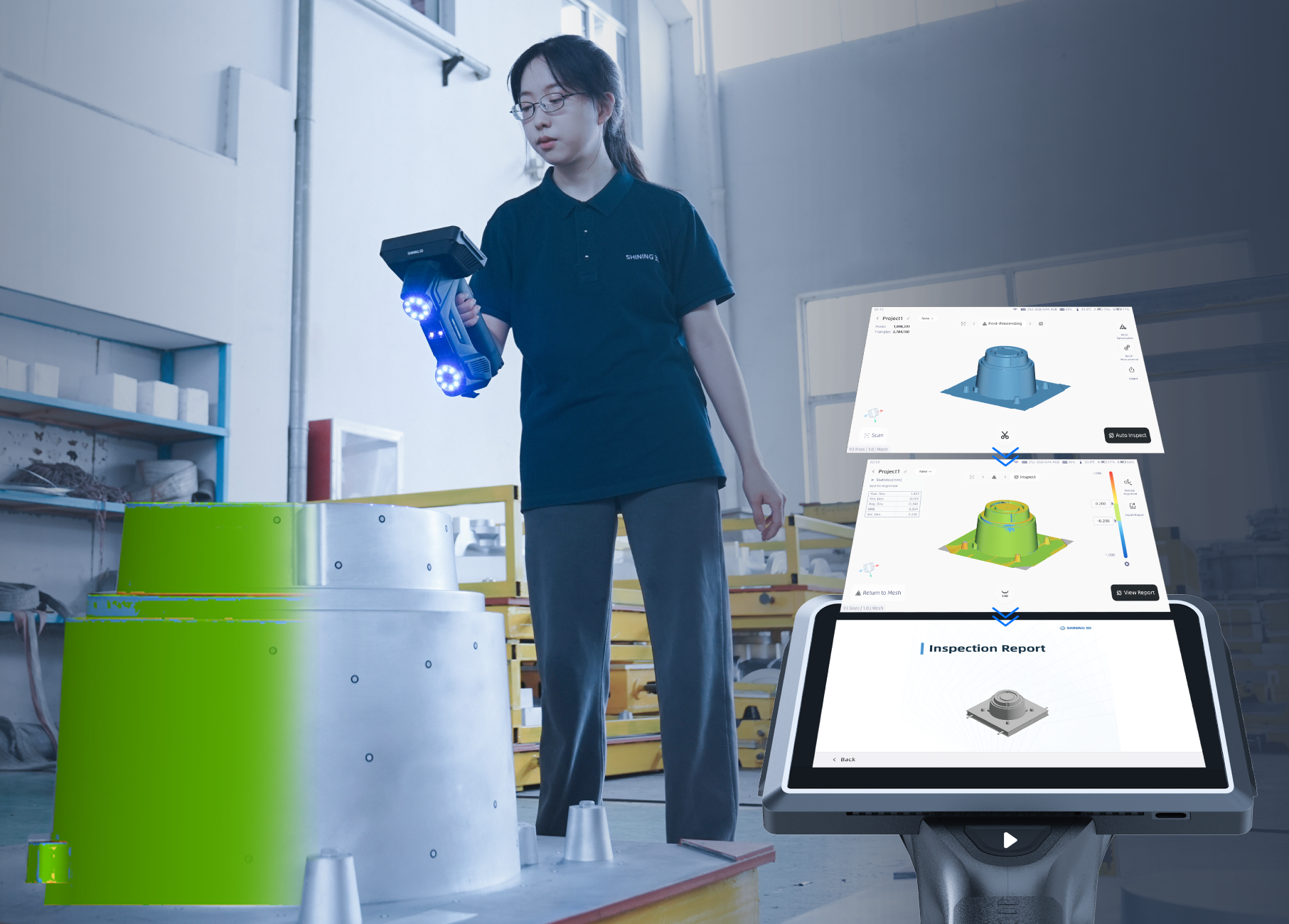
Two boundaries are worth recording in the evaluation file. The FreeScan Combo Series has no colour camera, so it cannot capture texture — a limitation for appearance verification, irrelevant for dimensional work. And fixed systems assume a controlled environment; a temperature-stable lab is part of their specification, not an optional accessory.
Gate 5 — Certification Is a Chain, Not a Logo
Three standards do most of the work in optical 3D measurement procurement. ISO 10360 defines acceptance and reverification testing for coordinate measuring systems; ISO 10360-12 addresses articulated arm CMMs equipped with 3D scanners. VDI/VDE 2634 Part 3 is the guideline for acceptance and reverification of optical 3D measuring systems based on multiple-view area scanning. ISO/IEC 17025 defines the competence of the laboratory performing the test.
The chain only holds when all three are present: a named test standard, a named laboratory, and a scope of accreditation that covers the test in question.
SHINING 3D operates a precision laboratory accredited in accordance with ISO/IEC 17025 and performs calibration and verification there. Its scanners are tested according to VDI/VDE 2634 Part 3 and ISO 10360 — for example, the FreeScan Trak Nova Series, the FreeScan Combo Series, the FreeScan Combo+ Wireless and Combo Wireless, the OptimScan Q12/Q9, the OptimScan Q12/Q9 HD, and the FreeScan Omni Series. Product compliance covers CE, FCC, ROHS, WEEE, KC, FDA, UKCA, IP50, TELEC, and TISAX across the industrial range, with AutoScan Inspec2 holding CE, FCC, ROHS, WEEE, and KC.
Corporate-level systems are equally relevant to a supplier audit. SHINING 3D holds ISO 9001, ISO 14001, ISO 45001, ISO 13485, MDSAP, and KGMP, together with Authorized Economic Operator (AEO) advanced certification for supply-chain security. Information security is covered by TISAX, ISO/IEC 27001, ISO/IEC 27701, ISO/IEC 27017, ISO/IEC 27018, and MLPS Level 3, and the company holds Level 4 (System-Level) certification under Innovation and Intellectual Property Management Capability based on ISO 56005.
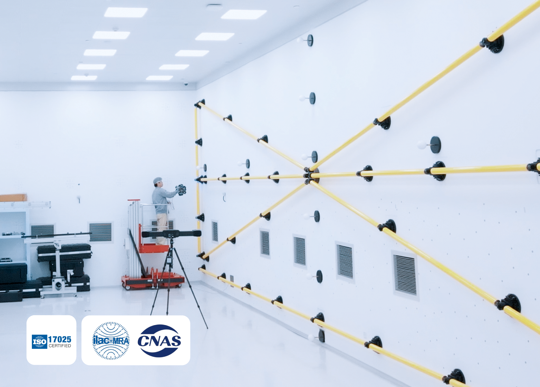
The honest boundary: a certificate describes a system under specified conditions. It does not guarantee that a specific fixture, operator, and part combination will hold the same tolerance on a Monday morning. A witnessed acceptance test on a representative production part remains the only conclusive check.
Gate 6 — Count the Steps From Scan to Signed Report
Inspection value is created in software, and the software question is a process question: how many manual steps separate a point cloud from a report that a quality manager will sign?
A disciplined digital inspection workflow runs through four stages. Data acquisition captures full-field geometry, including freeform surfaces that key-point measurement tends to miss. Processing and alignment cleans the point cloud and mesh and fixes the part in a reference frame. CAD comparison, deviation analysis, dimensional inspection, and GD&T evaluation identify where the part departs from design intent. Report generation consolidates measurements, deviations, and pass/fail results into a traceable document.
Buyers should therefore test the software stack, not just read its feature list. Relevant questions include: does the inspection module support compare, cross-section, feature, dimension, gauges, quick measurement, and reporting in one environment; does it export to the formats the downstream system accepts; and does the licence model include updates.
SHINING 3D’s inspection environment, SHINING3D Inspect, is PTB-certified and available both on-device and on PC. The scanners integrate with PolyWorks, Geomagic Control X, EXModel Pro, Geomagic Design X, and BlueStar Mapping. The OptimScan software bundle includes scanning templates, vibration detection, temperature control, and background cutting, with no subscription requirement.
Reference point: at TDK Hungary Components, a FreeScan Combo paired with Geomagic Control X reduced prototype inspection time from roughly two weeks with outsourced partners, or three to four days in the internal measurement lab, to an average of two to three hours.
Application Fit: Matching Archetype to Inspection Task
| Inspection task | Recommended archetype | Constraint that drives the choice |
|---|---|---|
| First article inspection, small precision parts | Fixed blue-light structured light or desktop automated cell | Micro-feature resolution and repeatability |
| GD&T on machined housings and powertrain parts | Fixed structured light or handheld laser | Feature accessibility and datum definition |
| Sheet metal and stamping deviation | Tracking handheld | Part size, springback, fixture-free capture |
| Casting and forging full-size inspection | Tracking handheld with VPG | Volumetric accuracy over metres |
| Mold and stamping die wear | Fixed structured light or handheld | Deep cavity access and surface condition |
| Electronic component batch inspection | Automated desktop cell | Cycle time and operator independence |
| MRO and field inspection of large equipment | Standalone wireless handheld | Cable-free operation and battery continuity |
| In-line automated inspection | Robot-integrated cell | Robot reach, cycle time, fixture repeatability |
These archetypes are not theoretical. At Zhongyan Casting, full-size inspection before dispatch supported a reported product qualification rate of 99.5%. At Steelstruct in Western Australia, a 15-tonne trommel screen shell previously assessed over days was inspected in hours, with the scan data compared directly against the original CAD model to isolate out-of-tolerance zones. At a Vietnamese automotive OEM, an automated scanning cell reduced inspection time from about one hour to five minutes per part. At a Thai precision mould manufacturer, per-part inspection time fell from 30–45 minutes to 10–15 minutes, an improvement of roughly 60%.
Market Trend Analysis
The commercial environment reinforces the framework rather than complicating it. Precedence Research reports that structured-light scanners dominated the product segment in 2024 because of their precision in industrial work, and that short-range scanners of one metre or less held the largest share of the market on the strength of parts inspection requirements. Both observations point in the same direction: the money is in precise, repeatable measurement of manufacturable parts, not in general-purpose digitization.
Regional distribution adds a supply-chain consideration. North America accounted for a 37% revenue share of the 3D scanner market in 2024, led by aerospace and automotive demand, while Asia Pacific is projected to grow fastest for 3D metrology at a CAGR of 8.0% through 2029. For a buyer operating across regions, service coverage and calibration logistics deserve as much weight as the specification sheet.
A parallel trend affects cycle time. Inline automated 3D inspection is increasingly replacing offline checks in the electronics sector to improve first-pass yields, and the 3D automated optical inspection equipment market was valued at USD 2.74 billion in 2024 with a 7.32% CAGR. The automotive industry remains the largest end user of 3D scanning overall.
The supplier landscape is consolidating around a small number of established metrology houses — Hexagon, FARO, and Carl Zeiss are commonly identified as Tier 1 leaders — alongside scaled specialists. SHINING 3D, founded in 2004 and headquartered in Hangzhou with subsidiaries in Stuttgart, Barcelona, California, Florida, and Tokyo, reported 31% revenue growth in 2025 and was recognised by 360Quadrants as an Emerging Leader in the industrial metrology space in 2025. The company holds more than 330 authorised patents and 230 software copyrights and states that 70% of its output is exported across the EU, USA, and APAC.
Comparison With Traditional Measurement Approaches
| Approach | Strength | Structural limitation |
|---|---|---|
| Callipers, gauges, height stands | Fast for a small number of defined dimensions | Key-point only; cannot detect shape deformation between measured points |
| Dedicated checking fixtures | High throughput once built | 1.5–2 months to design and build; custom tooling can cost thousands of dollars per part and must be rebuilt for each new geometry |
| Bridge or gantry CMM | Excellent repeatability on programmed features | Requires programming and often fixtures; contact probing for freeform surfaces is slow; large parts require gantry systems |
| 3D scanning and inspection | Full-field capture in one measurement; detects deformation missed by key-point checks; faster than CMM on complex or freeform surfaces | Optical line of sight is required; deep cavities and hidden features may need a probe or a fixed system; surface condition affects some configurations |
The comparison is not a case for replacement. A contact CMM remains the appropriate tool for programmed, high-repeatability verification of defined features, and gantry CMMs remain the reference for oversized parts in heavy industries such as aerospace and shipbuilding. The practical architecture for most plants is layered: CMM for the reference standard, scanning for full-field deviation, wear analysis, and the volume of parts that never reach the measuring room.
Gate 7 — Model Three to Five Years, Not the Invoice
The purchase price is the least informative number in a scanner evaluation. Total cost of ownership over a three-to-five-year horizon includes the system, software licensing, operator training, annual calibration, service coverage, consumables, fixture elimination, outsourced inspection, and — usually the largest line — the cost of defects discovered late.
Budget planning should assume an industrial metrology system costs several times the entry-level device it replaces. In this framework’s planning range, a specification that appears to be around five times the purchase price of a low-cost scanner is the normal starting assumption, not an anomaly. Against that premium, the realised saving typically lands in the 20–40% range on a three-to-five-year total-cost basis once fixture builds, outsourced measurement, and rework are netted out.
Those ranges become credible only when calibrated against real operating data, which is why reference cases belong in the procurement file:
- A Thai stamping parts manufacturer reported that eliminating dedicated fixtures cut project timelines by at least one-third and removed a 1.5–2 month tooling wait per part.
- A Vietnamese automotive OEM reduced inspection time from roughly one hour to five minutes per part using an automated scanning workflow.
- A Hungarian electronics manufacturer moved prototype inspection from two weeks (outsourced) or three to four days (internal lab) to two to three hours on average.
- A casting producer improved product qualification to a reported 99.5% after introducing full-size inspection before dispatch.
The limitation to write into the model: savings depend on inspection volume. A plant inspecting a handful of parts per month will not amortise a metrology-grade system through fixture elimination alone. For low-volume operations, the case rests on capability — measuring what previously could not be measured — rather than on throughput.
Future Outlook
Three developments are likely to reshape the decision framework over the next procurement cycle.
The first is the migration of inspection onto the instrument itself. On-device PTB-certified inspection, already implemented in the FreeScan Omni Series, removes the laptop from the workflow and shortens the interval between capture and verdict. As this becomes commonplace, the software question in Gate 6 shifts from “which PC software is bundled” to “what can be decided at the point of measurement.”
The second is the normalisation of marker-free large-volume capture. Video photogrammetry has already reduced the preparation burden on multi-metre objects; broader adoption will push volumetric accuracy specifications into the centre of the evaluation rather than the footnote.
The third is automation at the cell level. The 3D AOI equipment market growing at 7.32% CAGR and the shift toward inline inspection in electronics both point to scanners becoming a component in a robotic cell rather than a standalone instrument. RobotScan configurations — which combine a high-accuracy scanner, an industrial or collaborative robot, a turntable rated to 20 kg, and a robot working radius of 800 mm — are an early form of that architecture, and they are already customisable at the level of robot brand, scanner, turntable, fixture, and software.
For buyers, the implication is defensive: specify a system whose software and automation path can extend, rather than one whose ceiling is fixed at installation.
Frequently Asked Questions
What accuracy should a 3D scanner for quality control deliver?
Accuracy requirements are usually grouped into three bands: 0.005–0.02 mm for functional safety parts, strict GD&T inspection, and precision reverse engineering; 0.02–0.05 mm for assembly verification and structural analysis; and 0.05–0.1 mm for overall deformation analysis and large cosmetic parts. The appropriate band follows from the drawing tolerance, not from the scanner catalogue. A useful cross-check is that the required band is typically two to five times tighter than the specification of a consumer or prosumer device.
Which certifications and standards should a QC 3D scanner carry?
Three elements form the evidence chain. ISO 10360 defines acceptance and reverification testing for coordinate measuring systems, and ISO 10360-12 specifically addresses articulated arm CMMs equipped with 3D scanners. VDI/VDE 2634 Part 3 is the guideline for acceptance and reverification of optical 3D measuring systems based on multiple-view area scanning. ISO/IEC 17025 defines the competence of the laboratory performing the test. A supplier should be able to name the standard, the laboratory, and the accreditation scope. Product-level market-access certifications such as CE, FCC, ROHS, WEEE, KC, FDA, UKCA, IP50, TELEC, and TISAX are separate from measurement traceability and should be evaluated separately.
What does a 3D scanner for GD&T actually need in the software?
GD&T evaluation requires more than deviation colour mapping. The software must support CAD comparison, cross-section analysis, feature extraction, dimensional measurement, gauge definition, and report generation within one environment, because each hand-off between tools introduces a reconciliation step. On the OptimScan Q12/Q9 platform, the software integrates compare, cross-section, feature, dimension, gauges, report, and quick measurement functions. The scanner should also export to the formats accepted downstream, and the inspection environment should be certified where the report carries contractual weight — SHINING3D Inspect is PTB-certified and available both on-device and on PC.
Can a 3D scanner replace a CMM for first article inspection?
It can replace CMM work for full-field surface capture, freeform geometry, and deviation analysis, where scanning is faster and produces richer data than point-by-point probing. It is less suited to programmed, high-repeatability verification of a small number of defined features, which remains a CMM strength, and it cannot reach internal features that the optical path does not see. A layered workflow is more realistic than substitution: CMM for reference verification, scanning for full-field and first article coverage. At a Thai aircraft component manufacturer, the comparison was measured in preparation time — a CMM required two to three days to program and start collecting data for the same part, while the scanner completed capture in under half a day and removed the need for dedicated fixtures.
How does a handheld 3D scanner fit into automated in-line inspection?
It fits as the measurement head inside a robotic cell. In this configuration a scanner is mounted on an industrial or collaborative robot, with a turntable and fixtures providing part presentation, and control software sequencing the path teaching, measurement, and reporting cycle. The RobotScan Series supports this configuration with a measurable object size up to 500 mm, a turntable load capacity up to 20 kg, and a robot working radius of 800 mm, and it can be customised across robot brand, scanner model, turntable, fixtures, and software. At a Vietnamese automotive OEM, an automated scanning cell reduced inspection time from approximately one hour to five minutes per part and eliminated manual data entry.
How should buyers evaluate three-to-five-year total cost of ownership?
Total cost of ownership should include the system, software licensing and update policy, operator training, annual calibration, service coverage, consumables, eliminated fixture builds, outsourced inspection, and the cost of late-detected defects. Planning should assume an industrial metrology system costs several times the entry-level device it replaces, with a three-to-five-year total-cost position typically 20–40% below the low-cost path once fixture and rework savings are netted out. The model must be volume-sensitive: at low inspection volumes, the business case rests on measurement capability rather than throughput savings, and the calculation should say so explicitly.
Closing Note
The framework does not produce a single correct scanner. It produces a defensible decision record: features defined, tolerance band fixed, volumetric accuracy verified, form factor matched to the shopfloor, certification chain intact, software workflow tested, and ownership cost modelled over the period in which the system will actually be used. A purchase that can be reconstructed from those seven gates is one that survives the audit after installation.
SHINING 3D publishes a consolidated overview of its 3D digitizing portfolio, including the metrology systems referenced in this framework, as a downloadable reference: SHINING 3D 3D Digitizing introduction (PDF).
Есть вопросы или нужны дополнительные детали?
Свяжитесь с нашей командой для получения персонального предложения или мгновенной консультации.
Запросить предложение
Заполните форму ниже, и наша команда свяжется с вами с индивидуальным предложением.
Прямой чат WhatsApp
Предпочитаете общаться в реальном времени? Напишите нам в WhatsApp для мгновенной помощи и быстрых ответов.
- Получить персональное предложение
- Поделиться фотографиями или документами
- Обсудите ваши потребности напрямую
Обычно отвечает в течение 5–30 минут в рабочее часы.