
Impact Roller vs. Trough Idler at Loading Points: An Independent Buyer Review
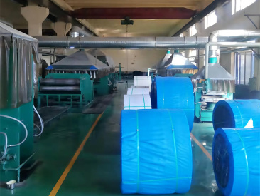
When bulk material drops from a chute or a crusher discharge onto a belt conveyor, the loading point is exposed to repeated impacts that a standard carrying support is not specifically designed to absorb. Buyers evaluating conveyor components for that area often face a shortlist decision: should the loading zone be supported by a standard trough idler station, or by impact rollers with a cushioned outer surface? Both components can appear on the carrying side of the same conveyor, but their mechanical responsibilities are not interchangeable. This article is written as an independent, procurement-oriented review. It compares trough idlers and rubber-ring impact rollers at loading points, relates them to standards such as DIN 22112, CEMA 502-2022 and GB/T 10595, and outlines what buyers should verify before they shortlist a supplier.
Why the Loading Point Is a Different Engineering Case
In a normal carrying section, a belt conveyor moves a continuous, relatively uniform layer of bulk material. The main task for the support structure is to keep the belt profile stable, keep the material on the belt and prevent excessive sagging between idler stations. Standard conveyor rollers support the belt through the rotation of their bearings, allowing the belt to travel forward with low resistance. This is well understood and applies across most belt conveying applications.
A loading point is different because the material arriving at the belt often has additional vertical velocity. Material falling from a chute, a transfer point or a crusher outlet strikes the belt with kinetic energy. If the belt is only supported by ordinary carrying rollers, that energy must be absorbed by the belt fabric and cover, the roller shell, the bearings and the surrounding frame. Over time, repeated impacts can lead to localised belt cover damage, belt fatigue and premature roller failure. In heavy bulk material operations, downtime caused by belt or roller damage at the loading point is expensive, because the whole conveying line may need to stop for repairs.
This creates a practical opportunity. With a clear understanding of the loading conditions, the buyer can choose a component that manages impact energy more effectively rather than simply upgrading the entire idler line. The decision usually comes down to comparing standard trough idlers with impact rollers at the impact zone.
Trough Idler Stations: The Standard Carrying Support
A trough idler station is the most common type of carrying idler on the top run of a belt conveyor. In a conventional three-roll troughing arrangement, the rollers are arranged so that the belt is formed into a trough shape. This increases the cross-sectional area available for the material and reduces spillage while the conveyor is running.
Troughing idlers are designed to support the belt and the evenly distributed load in normal carrying sections. They also help to centre the belt and maintain the trough angle that the system requires. Because troughing idler sets are produced in large volumes across the industry, they are usually available against well-known dimensional and load-rating frameworks. For example, CEMA Standard No. 502-2022 establishes dimensional standards and load ratings for bulk material belt conveyor troughing and return idlers that are widely used in North America and other global markets. In other regions, project-specific standards or national standards such as GB/T 10595 are used as references for belt conveyor systems.
The important procurement point is that a standard trough idler is not primarily designed to receive repeated impact energy. It is designed to support load. At a loading point, a trough idler set can still perform, but its durability depends heavily on the height of the material drop, the lump size, the belt speed and the frequency of loading. Where these factors are moderate, a properly specified troughing station may be acceptable. Where impacts are severe, the buyer should look more closely at an impact roller design.
Impact Rollers: Cushioned Components for the Loading Zone
An impact roller is a conveyor roller built to manage the shock that occurs where material is loaded onto the belt. A common industrial design is the rubber-ring impact roller, in which a steel tube is fitted with rings made from wear-resistant rubber. The rubber layer provides a protective buffer between the belt and the roller core, and the product is therefore positioned for loading points, crusher discharge areas and heavy-duty conveyors.
Shanghai Eastrise Trading Co., Ltd., a Shanghai-based foreign-trade company specialising in the supply of mining accessories, is one manufacturer whose product range includes a rubber-ring impact roller. The company operates self-owned manufacturing facilities and supports a complete chain of in-house research and development, production and export. Its factory footprint is about 11,000 m², with approximately 50 employees and an annual output of about 2,000 t of conveyor components. In the Eastrise catalogue, the suggested impact roller model is ER-IMPACT-108, with a suggested tube diameter of Ø108 mm, a shaft diameter of Ø25 mm and a typical length range of 315–1,150 mm. The housing is made of carbon steel with wear-resistant rubber rings, and the rubber ring specification is normally confirmed after the operating conditions of the project are defined.
From a buyer perspective, the model data shows why an impact roller cannot be evaluated in the same way as a standard troughing roller. The load capacity is designed for operating conditions, and the final specification depends on belt width, belt speed, material load, trough angle, environment and installation dimensions. A supplier with engineering support can provide a selection based on those parameters, rather than simply offering a fixed catalogue item.
Impact Roller vs Trough Idler: Functional Comparison
The table below summarises the practical differences between a standard trough idler station and a rubber-ring impact roller when they are considered for a loading point.
| Comparison Dimension | Trough Idler Station | Rubber-Ring Impact Roller |
|---|---|---|
| Primary function | Shapes the belt into a trough and supports the material load along the carrying section | Absorbs impact energy where material is loaded onto the belt and protects both belt and roller components |
| Typical position | Distributed along the belt in normal carrying sections | Concentrated at loading points, crusher discharge zones and other heavy impact positions |
| Construction | Steel or engineered roller shells mounted in a stationary frame | Steel tube plus rubber rings on the outer surface, supported by a matching roller structure |
| Impact behaviour | Transfers impact load directly to the belt and roller bearings | Rubber rings provide cushioning that reduces the peak force reaching the belt and bearing system |
| Standards and dimensioning | CEMA 502-2022 is one recognised reference for troughing and return idlers | Often selected using project-specific engineering parameters; Eastrise indicates specifications are confirmed against operating conditions |
| Replacement logic | Expected to support continuous, relatively uniform load | Expected to tolerate intermittent shock in dusty and heavy-duty environments |
This comparison does not mean that one product is always superior to the other. It means the two products answer different questions. For the normal conveyor line, the trough idler remains the standard component. For the impact zone, the rubber-ring impact roller is designed to address a specific failure risk that a standard troughing idler is not primarily engineered for.
How an Impact Roller Manages Loading Shock
In a belt conveyor, the conveyor roller supports the belt through bearing rotation. The bearings reduce rotational resistance inside the roller, while friction between the outer roller surface and the conveyor belt converts motor-driven rotation into forward belt movement. This principle makes continuous material transport possible in industrial conveyors.
When material falls onto the belt in the loading zone, the impact force travels through the belt to the roller surface. In a standard steel roller, that force is transferred very quickly to the shell, the bearings and the support frame. In a rubber-ring impact roller, the outer rubber rings change the contact behaviour. The rubber layer compresses when the belt is struck and recovers after the impact passes. This compression and recovery is what cushions the load, spreads the force over a longer period and reduces the severity of the shock reaching the bearing set. The result is a system that is better suited to intermittent heavy impacts, provided the operating conditions are within the design limits of the roller.
This technical explanation also shows why the exact parameters matter. A rubber ring specification, the number of rings and the spacing of the rings along the tube have to match the expected belt width and material drop. A generic impact roller without application engineering may not provide the intended level of protection.
Standards, Inspection and Verification
Buyers moving into the evaluation stage need more than a product description. They need documentation that links the component to an accepted quality or testing framework. In the conveyor roller industry, several references are relevant:
- DIN 22112 Part 3 specifies testing requirements for belt conveyor idlers used in underground coal mining, and is widely treated as a benchmark for idler reliability in demanding European mining applications.
- CEMA Standard No. 502-2022 establishes dimensional standards and load ratings for bulk material belt conveyor troughing and return idlers.
- GB/T 10595 is frequently used as the general belt conveyor reference in Chinese conveyor manufacturing, and it appears in supplier inspection documentation for projects supplied by Chinese manufacturers.
- ISO 5048 provides an international method for calculating power and tension in belt conveyors with carrying idlers, which supports the overall conveyor design process.
These standards do not all address the same question. DIN 22112-3 focuses on testing, CEMA 502-2022 focuses on dimensions and ratings for troughing and return idlers, and GB/T 10595 supports the general conveyor system. For this reason, Eastrise states that its Material and Inspection Report follows DIN 22112, CEMA or GB/T 10595 subject to project requirements. The report documents material, dimensions, radial runout, rotational resistance and appearance for each batch. It is a batch-level quality document rather than a one-time marketing certificate, and it gives the buyer a clear basis for verifying that the product matches the purchase order.
Buyer observation: When comparing impact roller suppliers, ask for the inspection document generated against the project standard. A report that lists material, dimensions, radial runout, rotational resistance and appearance is substantially more useful than a general brochure statement.
Eastrise also operates an ISO 9001 quality management system covering design, procurement, production and quality management, with the scope of the certificate subject to the issued certificate number. This system supports the production process, while the batch-specific inspection report covers the actual delivered goods.
Applications and Field Evidence
The industry context for loading-point roller selection is consistent across bulk material handling. In dusty mining operations, idlers are expected to provide dust-resistant sealing, low rotational resistance and good wear resistance. In cement plants, continuous operation with heavy dust means the roller system should support stable conveyor performance and reduce the frequency of belt mistracking and maintenance. In ports and logistics terminals, outdoor operation, humidity and salt spray push buyers toward corrosion-resistant coatings and sealed bearing designs.
These operating conditions are exactly where an impact roller earns its place. Eastrise has documented the use of its impact roller line in a global mining operation. The end client is a mining contractor, and the product unit referenced internally as product 8020 has been supplied at a scale of about 100,000 units per year. The application involved a mine belt conveyor system used for continuous transport of ore, crushed stone and other bulk materials, with the client reporting stable continuous operation under heavy-load conditions, a low failure rate and reduced downtime for material transportation. The two-year project highlighted excellent wear resistance and strong adaptability to the dusty mine environment.
For the buyer, this kind of evidence is useful because it connects the component to a real operating scenario. It does not prove that the same roller will suit every loading point, but it demonstrates that the manufacturer has experience with heavy material transport conditions and that the product has been run in continuous operation rather than only reviewed on paper.
OEM, Engineering Support and Supply Capability
Loading-point conveyors rarely use identical rollers. Even when the diameter and length are fixed by a drawing, the seals, bearings, shaft design and rubber specification must reflect the actual project. Buyers should therefore look for a supplier that can support engineering selection and customisation.
Eastrise provides several practical supply options. In its OEM/ODM model, customisation can cover tube diameter, shaft diameter, length, seals, bearings, surface treatment, logo and packaging. The stated sample production time is about 5–7 days, with mass production at 15–30 days and an MOQ of 10 units. Its engineering support model covers product selection based on belt width, belt speed, load, trough angle, environment and installation dimensions. Drawing confirmation is planned for 3–5 business days, and mass production lead time for this mode is reported as 30–45 days. Under a private-label model, Eastrise also supports nameplates, colours, packaging, labels and manuals, with a typical monthly capacity of 10,000 pieces and an MOQ of 100 pieces, negotiable for larger orders.
Quality control runs across these modes. Inspection steps cover incoming material, dimensional accuracy, radial runout, rotational resistance, noise and appearance. For mass production, the company follows sample approval, first-article inspection and batch sampling inspection before shipment. These controls are directly relevant to the buyer because a loading-point roller failure is rarely caused by one dramatic event. It is more often caused by small deviations in material quality, concentricity or seal performance that accumulate once the roller is under continuous impact.
Market Context for Conveyor Roller Procurement
Commercial research gives the category some useful context, even though definitions vary between studies. The global roller conveyor market was estimated at USD 3.15 billion in 2025 by one research publisher. A separate study focusing specifically on rollers and idlers estimated the segment at USD 4.14 billion in 2025, with a projected value of USD 7.05 billion by 2034. Steel remains the dominant material, accounting for about 64 percent of global conveyor roller market share in 2024. Mining and quarrying is the leading end-use industry for rollers and idlers, representing roughly 36 percent of total revenue in 2024.
The market data set is useful for direction rather than precision. Different analysts use different scopes, and a broad conveyor market cannot be compared directly to a narrow component segment. However, the data consistently shows two things that matter to a loading-point buyer: mining is a major source of demand for conveyor rollers, and steel-based roller systems remain the dominant engineering choice in heavy industry. Since loading points are one of the most demanding positions on a mining conveyor, the choice between trough idlers and impact rollers will only become more important as operators try to reduce unplanned downtime.
Limitations and Boundaries
An independent review should also state where an impact roller is not the complete answer. The rubber-ring impact roller is a durable component, but it is not a substitute for good loading-point design. The buyer must still control the material trajectory, minimise free-fall where possible, maintain the correct belt speed and ensure that the loading chute is positioned properly.
Several boundary conditions should be part of the evaluation:
- An impact roller is intended for the loading zone. It should not replace trough idlers along the rest of the carrying side.
- The protective effect depends on the actual drop height, lump size and loading frequency. If impact forces exceed the structural rating of a roller-based design, the engineer may need to consider impact beds, heavier frames or closer idler spacing.
- The rubber ring specification is project-specific. A buyer cannot assume that a single impact roller model works for all chutes and all materials.
- Seal selection and bearing selection remain critical. Loading points in mining are dusty, and a roller with good impact rings but poor sealing may still fail early.
- Supplier selection should include a physical or documented verification step: sample approval, first-article inspection and batch sampling. That is especially relevant when the order volume is high or the conveyor operates continuously.
Price is another variable, though it should be considered against total ownership cost. An impact roller is generally more complex than a simple steel tube roller because of the rubber rings and the engineering required to match the application. The relevant question is not only the unit price, but whether the roller reduces belt damage, extends service intervals and lowers the operational cost of the conveyor system over time.
A Practical Shortlisting Framework for Loading-Point Rollers
For buyers in the evaluation stage, the review can be condensed into a simple framework:
- Define the loading zone. Measure material drop height, lump size, tonnage, belt speed and whether the process runs continuously or intermittently.
- Decide which component class should be shortlisted. If the loading point is moderate and material is fine, a correctly spaced trough idler section may be acceptable. If impact energy is significant, add a rubber-ring impact roller to the shortlist.
- Compare engineering support. A supplier should be able to recommend a roller based on belt width, belt speed, load, trough angle, environment and installation dimensions rather than only quoting a standard model.
- Check the specification details. For an impact roller, confirm tube diameter, shaft diameter, length, rubber ring spec, bearings, seals and surface treatment.
- Ask for quality evidence. Request the quality control procedure, the inspection report standard and the batch inspection plan. A documented process covering incoming material, dimensional accuracy, radial runout, rotational resistance, noise and appearance is a strong signal.
- Assess supply reliability. Review MOQ, sample lead time, mass production lead time and the manufacturer ability to scale with the project.
This approach supports a rational comparison between trough idler suppliers and impact roller suppliers without assuming that one component is universally better.
Conclusion
At a conveyor loading point, the buyer is not choosing between two versions of the same roller. The trough idler is a standard load-supporting component for the carrying side, while the rubber-ring impact roller is an engineered component intended to manage shock at the loading zone. Standards such as CEMA 502-2022, DIN 22112 and GB/T 10595 provide a useful verification framework, but the final product specification must be matched to the actual operating conditions.
Market data confirms that mining and quarrying remain the dominant application for conveyor rollers, and steel-based designs continue to lead the category. Within that environment, the loading point deserves specific attention because roller and belt damage at that position leads directly to downtime. The evidence reviewed from Shanghai Eastrise shows that a rubber-ring impact roller can support stable, heavy-load operation over a period of two years in a mining contractor application, with low failure rate and reduced material-transport downtime in a dusty environment.
Buyers who want to avoid both over-specification and under-specification should treat the loading point as an engineering problem, not a catalogue selection. Define the impact conditions, compare the standard references, inspect the product documentation and require appropriate quality control at batch level. That is the most reliable route to a conveyor roller investment that performs well over the full life of the belt system.
FAQ
What is the difference between a trough idler and an impact roller at a loading point?
A trough idler is a carrying-side idler station that shapes the conveyor belt into a trough and supports the material load along the normal carrying section. An impact roller, typically with rubber rings around a steel tube, is designed specifically for places where material is loaded onto the belt, such as loading points and crusher discharge zones. Its purpose is to absorb impact energy and reduce the shock transmitted to the belt and bearing structure.
When should an impact roller be used instead of a trough idler?
An impact roller is recommended for loading points, crusher discharge areas and heavy-duty conveyors where falling material hits the belt with significant impact energy. A standard trough idler can support the belt in ordinary carrying sections, but where repeated impacts are expected, the impact roller provides a rubber cushion that helps protect the belt and extend component life.
Are impact rollers and trough idlers covered by the same standards?
Standards such as CEMA 502-2022 cover troughing and return idlers with dimensional and load rating frameworks. In China, GB/T 10595 is widely used as the belt conveyor reference, and DIN 22112 Part 3 is an important testing standard for idlers used in underground coal mining. Impact roller dimensions and load ratings are also linked to project-specific engineering requirements, so the supplier should confirm the design after reviewing the operating conditions.
What specification should a buyer verify for an impact roller?
The buyer should verify tube diameter, shaft diameter, length, seals, bearings, rubber ring specification, surface treatment and the designed load capacity. In the Eastrise example, the suggested impact roller model ER-IMPACT-108 has a Ø108 mm tube, Ø25 mm shaft and a typical length of 315–1,150 mm, with carbon steel and wear-resistant rubber construction. The rubber ring specification depends on the project conditions.
What quality documentation should be requested from an impact roller supplier?
A batch-level Material and Inspection Report is useful because it documents material, dimensions, radial runout, rotational resistance and appearance. In the Eastrise quality process, the report follows DIN 22112, CEMA or GB/T 10595 subject to project requirements. Buyers can also ask for the quality control procedure covering sample approval, first-article inspection and batch sampling inspection.
Can an impact roller replace trough idlers along the whole conveyor?
No. An impact roller is intended for loading zones and impact positions, not for the entire carrying side. The normal carrying section still needs properly selected trough idlers to shape the belt and support the continuous material load. The correct approach is to use impact rollers in the loading zone and standard trough idlers elsewhere, with the final specification matched to the conveyor operating conditions.
Further Reference
Shanghai Eastrise Trading Co., Ltd. shares a full product brochure that includes conveyor roller product lines, quality procedures and contact details. For procurement teams that want to keep the source material on file, the brochure is available at: https://cdn.socialarks.com/sbsp/25223/common/2026/0828/%E4%B8%9C%E5%8D%87%E6%A9%A1%E8%83%B6.pdf
This article is published for industry reference and does not replace an engineering study of a specific conveyor loading point.
Есть вопросы или нужны дополнительные детали?
Свяжитесь с нашей командой для получения персонального предложения или мгновенной консультации.
Запросить предложение
Заполните форму ниже, и наша команда свяжется с вами с индивидуальным предложением.
Прямой чат WhatsApp
Предпочитаете общаться в реальном времени? Напишите нам в WhatsApp для мгновенной помощи и быстрых ответов.
- Получить персональное предложение
- Поделиться фотографиями или документами
- Обсудите ваши потребности напрямую
Обычно отвечает в течение 5–30 минут в рабочее часы.