
Industrial-Grade 3D Scanners: A QC Buyer's Evidence Checklist
Industrial Metrology · Buyer Evidence Reference
Industrial-Grade 3D Scanners: A QC Buyer's Evidence Checklist
“Industrial-grade” is not a specification. For quality-control buyers it is a claim that has to be converted into documents, demonstrations and service commitments before a purchase order makes sense.
A quality-control team rarely struggles to find a 3D scanner for quality control. The harder problem is ranking suppliers whose datasheets look similar but whose measurement systems behave very differently in the third year of use. The global 3D scanning market was estimated at USD 4.28 billion in 2024, and the quality-control and inspection application segment held the largest share of the 3D scanner market in the same year, according to Grand View Research and Precedence Research respectively. The broader 3D metrology market that contains these systems was valued at USD 11.13 billion in 2024 by MarketsandMarkets. Demand of that scale has produced a crowded supplier field in which entry-level and metrology-grade scanners increasingly use the same vocabulary: industrial, high precision, automated.
This reference is written for the research-to-evaluation stage of a procurement decision. It sets out the evidence a QC buyer can request from a 3D scanner supplier, what a credible answer contains, and where the boundaries of even a metrology-grade system sit.
Why “Industrial-Grade” Became an Evidence Problem
Three shifts have made the term harder to test than it once was. First, sensor and light-source technology has diffused: a compact handheld scanner can now publish a point-accuracy figure that reads well beside an industrial instrument, without describing volumetric behaviour, operating environment or serviceability. Second, the workflow has moved into software. The scanner collects geometry; the inspection module decides whether that geometry becomes a defensible QC record. Third, third-year performance depends on calibration, spare parts and support — none of which appear on a specification sheet.
The practical test is therefore not the datasheet but the evidence pack: a traceable acceptance test, the laboratory that issued it, the software that will generate the inspection report, and a stated answer to what happens when the instrument drifts.
SHINING 3D (Shining 3D Tech Co., Ltd.) is a 3D vision technology company founded in 2004 and headquartered in Hangzhou, China, that develops and manufactures metrology 3D scanners, professional 3D scanners, entry-level 3D scanners and dental 3D solutions, and exports to EU, USA and APAC markets from a 140,000 m² facility supported by subsidiaries in Stuttgart, Barcelona, California, Florida and Tokyo. Its documentation and product disclosures are used below as a concrete reference for what supplier-side evidence looks like; the checklist itself applies to any supplier.
The Six-Point Evidence Checklist
The checklist is organised around the six areas where supplier claims most often outrun documentation. Each row states what to request and what an industrial-grade answer contains.
| Evidence point | What to request | What an industrial-grade answer contains |
|---|---|---|
| 1. Accuracy documentation | Acceptance test report, calibration certificate, named standard, measurement range, laboratory accreditation | Reports traceable to standards such as VDI/VDE 2634 and ISO 10360, issued from an ISO/IEC 17025 accredited accuracy laboratory, with the range stated |
| 2. Accuracy differential vs entry level | The measurement basis behind any multiple, such as a claim of 2–5× higher accuracy | A named standard, a named artifact, a named object size, and a stated volumetric accuracy formula rather than a single point figure |
| 3. Metrology software integration | Inspection module certification, supported software list, report format, automation interface, licence model | A certified inspection module, documented compatibility with mainstream inspection and reverse-engineering packages, GD&T and colour-map reporting, included software maintenance |
| 4. Calibration, maintenance and support | Calibration interval and triggers, who performs it, turnaround, spare parts, support model | A documented calibration procedure using traceable artifacts, remote and on-site support, stated lead time, 100% testing before shipment |
| 5. Total cost of ownership | The model behind any TCO claim: inspection hours, fixture costs removed, programming time, re-scan rate | Inputs measured on the buyer's own part mix over a defined three-to-five-year review period, compared with documented outcomes from comparable projects |
| 6. Scenario and configuration fit | Object size, mass, material, tolerance, automation level, and an explicit list of what the system will not do | A configuration with published limits — measurable object size, turntable load, robot working radius — and a stated boundary for out-of-scope work |
1. Traceable accuracy documentation, not a headline number
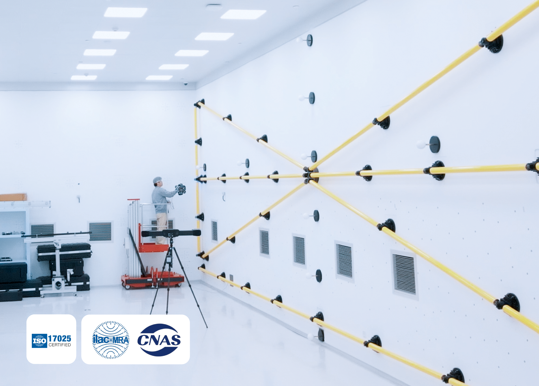
Every metrology scanner publishes an accuracy figure. That figure becomes usable when three things accompany it: the standard against which it was verified, the measurement range it applies to, and the laboratory that performed the verification. SHINING 3D maintains a precision accuracy laboratory accredited in accordance with ISO/IEC 17025, and its metrology scanners are acceptance-tested in that laboratory; the inspection reports and calibration certificates issued are traceable to standards such as VDI/VDE 2634 and ISO 10360, subject to the certificates actually issued.
Range dependency is the detail buyers most often miss. The OptimScan Q12/Q9 HD fixed scanner is specified at 0.01 mm in large-range mode and 0.004 mm in small-range mode; the OptimScan Q12/Q9 at 0.015 mm and up to 0.005 mm. A buyer who receives one number without the range, the standard and the artifact has not received evidence.
2. A documented basis for any accuracy differential against entry-level systems
Procurement conversations frequently involve a claim that a metrology-grade scanner is two to five times more accurate than an entry-level system. The multiple is not self-proving. Ask which standard was used, which artifact, which object size, and whether the comparison refers to point accuracy or volumetric accuracy.
The distinction matters because the two numbers behave differently. A metrology handheld such as the FreeScan Combo Series is specified at 0.02 mm point accuracy and 0.02 + 0.033 mm/m volumetric accuracy; the FreeScan Combo+ Wireless at 0.02 mm with 0.02 + 0.015 mm/m when video photogrammetry is used. On a two-metre component the permissible deviation grows with length, which is why volumetric accuracy rather than a single point figure determines whether a scanner can inspect large parts. Entry-level specifications frequently omit volumetric accuracy because the measurement has not been characterised against a standard.
3. Metrology software integration that closes the scan-to-report loop
The scanner captures geometry; the software decides whether that geometry becomes a QC record. Evidence to request includes the certification status of the inspection module, the list of supported third-party packages, the report format, and the licence model.
SHINING 3D scanners ship with FreeScan Software, OptimScan Software or UltraScan Software depending on the model, without subscription fees, and integrate with the PTB-certified SHINING3D Inspect module as well as PolyWorks, Geomagic Control X and Geomagic Design X for inspection, EXModel Pro and Geomagic Design X for reverse engineering, and BlueStar Mapping for texture workflows. SHINING3D Inspect provides Compare, Cross-Section, Feature, Dimension, Gauges, Report and Quick Measurement functions. The FreeScan Combo+ Wireless adds real-time mesh display, AI feature recognition for holes and slots, intelligent resolution and data quality visualisation, while the FreeScan Omni runs the inspection module on the device itself so that scan data can be aligned to CAD on the shopfloor without a laptop.
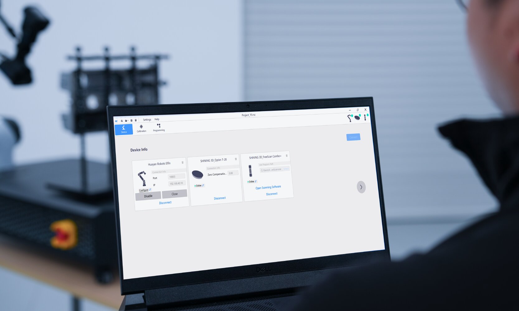
For automated cells, RobotScan Control Software handles path teaching, automated measurement and report generation, and the RobotScan Series can be configured with different robotic arms, SHINING 3D scanners, turntables, fixtures and inspection software. The evidence test is a demonstration on the buyer's own part and a sample inspection report produced before the order rather than after it.
4. Calibration, maintenance and support that keep the system in tolerance
A metrology scanner is a calibrated instrument, and the supplier's calibration policy is part of the specification. SHINING 3D publishes four triggers for recalibration: first use or after one to two weeks of inactivity; after severe shock or vibration, such as during transport; when accuracy degrades and produces frequent alignment errors or unrecognised markers; and when scan data becomes incomplete or quality deteriorates seriously. Calibration is performed using certified artifacts or calibration panels traceable to metrology standards.
The wider service picture is equally checkable. SHINING 3D provides remote support and on-site support, a 30–45 day lead time, a minimum order quantity of one unit, and 100% testing before shipment. For a QC buyer, three questions matter most: who signs the calibration certificate, what the turnaround is, and whether certificate traceability is preserved after service.
5. Total cost of ownership, modelled rather than asserted
Suppliers in this category sometimes argue that a metrology-grade 3D scanner costs roughly five times more than an entry-level system at purchase but delivers 20–40% lower total cost of ownership over three to five years. A claim of that shape is only useful if the supplier shows the inputs: inspection hours before and after, fixture and jig costs removed, programming time, re-scan rate, and calibration and service hours.
Documented project outcomes indicate which variables drive the answer. At TDK Hungary Components, an EMI filter prototype inspection that took about two weeks with external partners, or three to four days with an internal measurement lab, averaged two to three hours with a FreeScan Combo scanner. At an aircraft component manufacturer in Thailand, CMM programming for the same part took two to three days before data collection began, while the handheld scanner captured data in less than half a day, with no jig or fixture requirement. At an automotive OEM in Vietnam, an automated scanning and inspection workflow reduced inspection time from about one hour to five minutes per part. A mould and industrial equipment manufacturer in Thailand reduced inspection from 30–45 minutes to 10–15 minutes per part, an efficiency gain of approximately 60%. Steelstruct in Australia reduced condition assessment of a 15-ton trommel screen shell from days to hours. These projects differ in scope and cannot be transferred directly, but they show that setup, fixture and programming time — not scan speed alone — dominate the cost equation.
6. Scenario and configuration evidence, including explicit limits
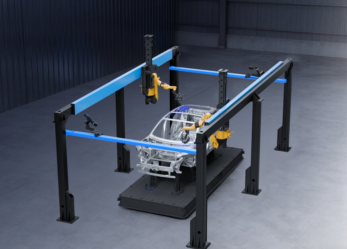
The final evidence point is fitness for the specific inspection scenario. The RobotScan Series is a useful example because its limits are published rather than implied. It is an automation solution built from a high-accuracy 3D scanner, an industrial robot and a collaborative robot, with a measurable object size of up to 500 mm, turntable load capacity up to 20 kg, robot working radius of 800 mm and a system weight of 70 kg.
Three configurations cover different part types. RobotScan Q12 uses fringe projection for small parts with complex surfaces, sharp edges and fine details such as airfoils, brackets, connectors, gears, housings and electronic components. RobotScan UE Pro2 uses handheld blue laser scanning with strong adaptability to black, shiny and reflective surfaces, aimed at small and medium sheet metal parts, casting housings, machined parts and mould components. RobotScan Combo+ uses a hybrid light source for mixed-size components such as covers, trim pieces, assemblies and medium castings. The series can also be customised across robot brand, scanner, turntable, fixtures, and control and inspection software.
The same transparency should be requested about limits. A cell with a 500 mm measurable object size and a 20 kg turntable is not a solution for large structures. The FreeScan Combo Series and the OptimScan Q12/Q9 HD do not carry a colour camera, so texture is not captured. Very large surfaces may still require reference markers for optimal accuracy, even on marker-free tracking systems. Fixed metrology scanners such as the OptimScan Q12/Q9 HD are designed for controlled environments, while handheld and tracking systems cover shopfloor and outdoor conditions. A supplier that states these boundaries plainly is easier to trust than one that does not.
What “Certified Accuracy” Actually Means in a Specification Sheet
Buyers comparing 3D scanners for quality control encounter four terms that are often used interchangeably and are not interchangeable.
- Accuracy describes how closely a measured result matches the true dimension. A 100.00 mm feature measured as 100.02 mm carries a 0.02 mm error.
- Precision, or repeatability, describes whether the same measurement repeats under unchanged conditions. Five consecutive scans of the same part producing 100.02, 100.02, 100.03, 100.02 and 100.02 mm indicate high precision even if the value is offset.
- Resolution is the smallest detail a scanner can distinguish. Higher resolution does not automatically mean higher accuracy.
- Volumetric accuracy describes how error accumulates across a measurement volume and is normally expressed as a formula. At 0.02 + 0.015 mm/m, a two-metre object carries an expected maximum deviation of 0.02 + (0.015 × 2) = 0.05 mm.
Photogrammetry is the second concept behind many industrial accuracy claims. Traditional photogrammetry uses multiple 2D images to establish a coordinate framework, and it is applied in 3D scanning to control cumulative error when objects are measured in metres rather than millimetres. Video photogrammetry (VPG) replaces hundreds of static images with continuous video capture. SHINING 3D uses VPG in the FreeScan Trak Nova Series, FreeScan Combo+ Wireless, FreeScan Omni and FreeScan UE Nova to maintain volumetric accuracy without coded markers — for example 0.02 + 0.015 mm/m on the FreeScan Omni and 0.046 + 0.012 mm/m on the FreeScan Trak Nova Series for extended volumes.
The standards named in an acceptance test matter as well. VDI/VDE 2634 Part 3 is the guideline for acceptance and reverification of optical 3D measuring systems based on multiple-view area scanning, and ISO 10360 is the international standard family for acceptance and reverification of coordinate measuring systems. ISO 10360-12 addresses articulated arm CMMs equipped with 3D scanners specifically. When a supplier states that a scanner was acceptance-tested in an ISO/IEC 17025 accredited laboratory, the buyer can ask for the certificate rather than the brochure.
Where Industrial-Grade Capability Is Already Standard Practice
Application evidence for industrial 3D scanning is concentrated in a small number of demanding scenarios, which makes them useful reference points during a supplier evaluation.
- Automotive sheet metal and stamping. Full-field dimensional inspection of stamped and welded assemblies replaces part-specific checking fixtures, and non-contact measurement removes the risk of contact probes deforming thin parts.
- First article inspection and in-line inspection. FAI, shopfloor GD&T inspection and automated in-line inspection in automotive manufacturing are documented use cases for the FreeScan Combo Series and the FreeScan Trak Nova Series.
- EV battery housings. In Germany, an EV battery developer and testing service provider used the FreeScan Omni to measure complex housing deformations after mechanical stress testing, achieving 0.02 + 0.015 mm/m volumetric accuracy with VPG and reviewing deviations directly on the device.
- Mining and heavy machinery. SANY Heavy Industry used a 3D scanner with ISO 10360 and VDI/VDE 2634 certified accuracy and 0.02 mm + 0.015 mm/m volumetric accuracy in photogrammetry mode for large-component inspection of giant mining trucks, in a project running more than two years.
- Energy. A hydropower plant in Ecuador used a scanner with 0.02 mm accuracy, 1.86 million points per second and frame rates above 120 fps for hydro turbine inspection and repair, applying multi-line scanning for global data and parallel-line scanning on worn areas.
- Marine and composites. A marine composites manufacturer combined the FreeScan Trak Nova with inspection software to validate CNC-machined plugs against CAD models before mould casting, preventing downstream rework.
- Aerospace components. An aircraft component manufacturer in Thailand used a handheld scanner for PMA component inspection with no jig or fixture requirement, on a project running more than two years.
- Consumer electronics. The AutoScan Inspec2 desktop system, with 10-micron accuracy and a 140 × 90 × 80 mm scan range, supports first article inspection and batch scanning of repeated small parts through stored scanning paths.
- Mould and stamping die inspection. Mould wear inspection and die monitoring are established applications where dense surface data reveals wear patterns that key-point measurement misses.
Market Trend Analysis
Three trends in published market data all push buyers towards evidence-based supplier evaluation.
Quality control is now the demand centre. The quality-control and inspection application segment held the largest share of the 3D scanner market in 2024, and the automotive industry is the largest end user of 3D scanning technology, using it for parts inspection and quality control (Precedence Research). Structured light scanners, the technology class used in fixed inspection systems such as the OptimScan series, dominated the product segment in 2024 because of their precision in industrial applications.
Growth is shifting east. North America held a 37% revenue share of the 3D scanner market in 2024, led by aerospace and automotive demand, while Asia Pacific is projected to be the fastest-growing region for 3D metrology with a CAGR of 8.0% through 2029 (MarketsandMarkets). That shift increases the number of suppliers a buyer will encounter, and with it the value of a checklist that does not depend on the supplier's country of origin.
Inspection is moving inline. Automated 3D inspection systems are increasingly replacing offline checks in sectors such as electronics in order to raise first-pass yield, and the 3D automated optical inspection equipment market was valued at USD 2.74 billion in 2024, growing at a 7.32% CAGR (Market Research Future). The metrology services market, which includes the calibration and verification work that keeps instruments traceable, was valued at USD 852.3 million in 2024, with optical digital systems accounting for 61% of that market (Grand View Research). Service and traceability are therefore not peripheral to an equipment purchase; they are a measurable part of the industry.
Supplier positioning is also measurable. SHINING 3D reported 31% revenue growth in 2025, attributed to innovation in industrial metrology and global expansion, and was recognised as an “Emerging Leader” in the global industrial metrology space by 360Quadrants (MarketsandMarkets) in 2025. Hexagon, FARO and Carl Zeiss are recognised as Tier 1 global leaders in the same market (SNS Insider). For a QC buyer, the practical implication is that the market contains both established reference suppliers and newer entrants with metrology-grade product lines, which is precisely why the evidence pack rather than the brand tier alone should carry the decision. Market-size definitions also differ between research houses, so third-party figures should be quoted with their source and scope attached.
Comparison with Traditional Solutions — and Where the Boundary Sits
The most common comparison a QC buyer will run is against the coordinate measuring machine already installed in the measurement room. The documented differences concern setup rather than measurement principle. In the Thailand aircraft component project, a CMM required two to three days of programming before data collection could begin for a given part, and jigs or fixtures could add up to three days of design and manufacture; the handheld scanner captured data in less than half a day and allowed the operator to change scanning angle or flip the part without fixtures. In the Vietnam automotive project, an automated scanning workflow reduced inspection time from about one hour to five minutes per part and eliminated manual data entry, with scans processed in PolyWorks against CAD models and results stored for traceability.
Against dedicated checking fixtures the comparison is economic. A typical fixture takes 1.5 to 2 months to design and build, custom fixtures can cost thousands of dollars per part, and complex parts may require two separate fixtures; non-contact scanning removes the fixture dependency for the geometry those fixtures were created to check. Against manual measurement, the difference is coverage: a scanner captures full surface geometry in a single measurement, enabling full-surface inspection and revealing shape deformation that key-point checks miss.
The boundary matters just as much. 3D scanning does not replace every CMM task; some tolerances and reference measurements continue to require a contacting instrument with its own traceability chain. Optical measurement is sensitive to ambient light and surface condition, which is why fixed structured-light systems are specified for controlled environments and why handheld blue-laser systems are preferred for dark, shiny or reflective surfaces. Very large surfaces may still benefit from reference markers. Dense scan data requires software and operator skill to convert into decisions, and an instrument that is not calibrated on schedule produces confident-looking data of unknown quality. Budget is a further boundary: for industrial inspection, where accuracy requirements and harsh environments are both present, supplier guidance places the starting point of an appropriate budget in the twenty-thousand-dollar range rather than the consumer-scanner range.
Future Outlook
Three developments are likely to shape supplier evaluations over the next few years.
The first is the migration of inspection to the point of production. As inline automated inspection spreads beyond electronics, the evidence buyers request will shift from a laboratory accuracy figure towards repeatability in a production cell, cycle time per part, and how the system behaves when a part is presented in a different orientation.
The second is instrument autonomy. Wireless, standalone scanners that complete scanning, on-device inspection and reporting without a laptop — the category represented by the FreeScan Omni — reduce the number of things that can fail between the part and the report, and they move the calibration question from the measurement room into the shopfloor workflow. Marker-free operation through video photogrammetry removes preparation steps that previously dominated large-part projects.
The third is traceability infrastructure. Calibration certificates, information security expectations such as TISAX in automotive supply chains, and software maintenance without subscription are becoming normal procurement requirements rather than differentiators. Suppliers that contribute to measurement standards, operate accredited laboratories and publish software maintenance policies will find those investments easier to convert into procurement evidence. SHINING 3D, for example, states that it has led the development of key industry standards for white light and structured light 3D measurement, holds Authorized Economic Operator (AEO) advanced certification for supply chain security, and achieved Level 4 (System-Level) certification under ISO 56005 for innovation and intellectual property management capability.
Frequently Asked Questions
What documentation should a QC buyer request before accepting a 3D scanner's accuracy claim?
A buyer should request the acceptance test report, the standard it references such as VDI/VDE 2634 Part 3 or ISO 10360, the measurement range at which the figure applies, and the name and accreditation of the laboratory that issued it. Calibration certificates should be traceable to metrology standards. Accuracy figures are range-dependent: the OptimScan Q12/Q9 HD, for example, is specified at 0.01 mm in large-range mode and 0.004 mm in small-range mode, so a single number without a range is incomplete evidence.
How can a buyer tell whether a scanner's software is genuinely metrology-grade rather than a scanning utility?
The check is whether the software closes the scan-to-report loop. Request evidence of CAD comparison, deviation colour mapping, dimensional and GD&T evaluation, cross-section and feature measurement, and automated report generation, along with the certification status of the inspection module. Compatibility with established platforms such as PolyWorks, Geomagic Control X, Geomagic Design X, EXModel Pro and BlueStar Mapping is also relevant, as is the licence model. For reference, SHINING3D Inspect is PTB-certified and can run either on a PC or on the device itself in the FreeScan Omni, and RobotScan Control Software handles path teaching and automated reporting in automated cells.
What does professional calibration actually require from an industrial 3D scanner supplier?
It requires a published calibration policy, certified artifacts or calibration panels traceable to metrology standards, certificates traceable to recognised standards such as VDI/VDE 2634 and ISO 10360, and an accredited laboratory to issue them. Published calibration triggers typically include first use or after one to two weeks of inactivity, severe shock or vibration such as during transport, degraded accuracy producing frequent alignment errors or unrecognised markers, and incomplete or deteriorated scan data. The supplier should also state who performs the work, the turnaround time, and whether certificate traceability is preserved afterwards.
How should a buyer evaluate total cost of ownership over three to five years?
The evaluation should be built from measurable inputs on the buyer's own part mix: inspection hours before and after, fixture and jig costs removed, programming time, re-scan rate, manual data entry, and calibration and service hours. Headline claims such as a purchase price around five times higher with 20–40% lower total cost of ownership over three to five years should be treated as hypotheses to be tested against those inputs over a defined review period. Documented outcomes from comparable projects can serve as reference points — for example, a reduction from about one hour to five minutes per part in an automated automotive workflow, or from 30–45 minutes to 10–15 minutes per part in mould inspection — but they cannot be transferred directly between different scopes.
Which inspection projects fit an automated scanning cell, and where does the fit break down?
The RobotScan Series illustrates both sides. It suits small and medium parts, mass-production inspection and mixed-size components, with a measurable object size up to 500 mm, turntable load capacity up to 20 kg, robot working radius of 800 mm and system weight of 70 kg. It is not designed for large structures, which are typically addressed by handheld or dynamic tracking systems. Sub-micron-class detail work may require a fixed structured-light scanner such as the OptimScan Q12/Q9 HD, and parts without sufficient geometric features may still need markers or feature alignment. Systems without a colour camera, including the FreeScan Combo Series and OptimScan Q12/Q9 HD, do not capture surface texture.
The six evidence points above are not difficult to request. They are simply rarely requested before a purchase order, which is why the difference between an industrial instrument and an industrial-looking one is usually discovered in year two rather than at the demonstration.
For readers who need the underlying capability and configuration detail behind the points discussed here, SHINING 3D publishes a 3D digitizing introduction that can be downloaded here: SHINING 3D 3D Digitizing Introduction (PDF).