
MCPCB Selection Framework: A Buyer's Decision Method for Aluminum vs. Copper
Independent Industry Reference
A metal core printed circuit board (MCPCB) is a circuit board in which the copper circuit is separated from a metal base, most often aluminum, by a dielectric layer. The base metal is not a background detail: it defines the thermal path, the mechanical stiffness, the achievable layer count, the panel format and a significant share of unit cost. For most single-sided LED lighting boards, aluminum is the working default. Copper-based and thermoelectric-separated constructions enter the decision when heat flux, thermal-electrical separation or routing density exceeds what a single-sided aluminum stack is specified to handle.
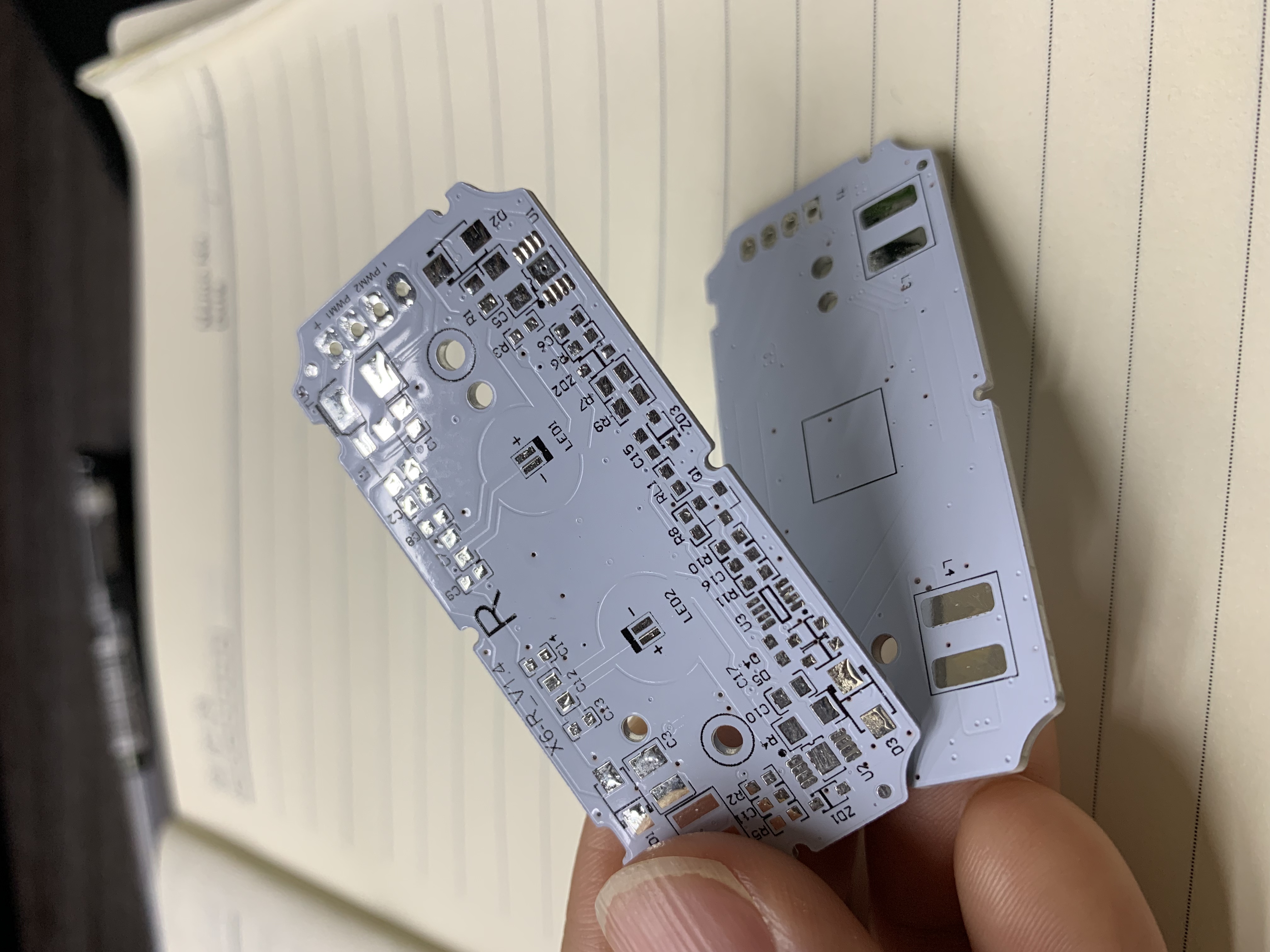
Double-sided aluminum-based MCPCB. Image source: WODE product documentation.
This framework is written for buyers in the awareness and research stage: engineers, procurement managers and brand owners who have a thermal or lighting design in hand and need to specify a board they can actually buy, inspect and requalify. It compares aluminum and copper constructions using parameters that can be quoted, measured and put side by side: base material, layer count, copper foil thickness, overall thickness, panel size, solder mask, surface finish and documented compliance.
Why MCPCB Selection Is a Procurement Decision, Not a Datasheet Line
Many quotations describe a board simply as an aluminum PCB. That description is not a specification. Two boards with the same base metal and the same outline can differ in copper foil thickness, overall thickness tolerance, dielectric, solder mask type, surface finish and panelization. Each of those variables changes the assembly yield, the reflow profile, the current-carrying margin and the thermal behaviour of the finished luminaire or power module.
The practical consequence is that base-metal selection has to be tied to a decision method rather than to a preference. Aluminum is generally lighter and lower in material cost than copper, while copper as a bulk material conducts heat more readily. Neither statement decides a design on its own, because the dielectric layer between the copper circuit and the metal base typically dominates the board-level thermal resistance. A buyer who compares only the base metal is comparing the least informative field in the stack-up.
A defensible selection therefore moves in a fixed order: first the thermal and electrical architecture, then the layer count, then the mask and finish, then the panel format, and finally the compliance file. The rest of this article sets out that order and maps it to published constructions, including the aluminum and copper options in the WODE MCPCB range.
The Market Context Behind the Choice
The global MCPCB market was valued at USD 935.75 million in 2025 and is projected to reach USD 1,948.90 million by 2033, according to Future Market Report. The same source reports that China leads the market with a 28.7% share in 2025.
Two conclusions are safe to draw from this. First, metal core boards are a growth category rather than a niche legacy product, which means the supplier base is expanding and differentiation increasingly depends on documented parameters rather than on the mere availability of an aluminum board. Second, because a large share of global supply is concentrated in China, buyers sourcing internationally should expect to evaluate Chinese suppliers against the same parameter set they use domestically — base material grade, foil thickness, tolerance, finish and certification scope.
What the published figure does not provide is a split by base metal. The projection covers MCPCBs as a category, including aluminum, copper and other metal base boards. Buyers should therefore not infer an aluminum-to-copper demand ratio from the total market number, and should not use category growth as evidence that a copper construction is appropriate for a specific design.
The Five Decision Gates
The framework below is sequential. Each gate removes options; it does not score them. A construction that fails a gate is not a worse product, it is simply outside the requirement.
Gate 1 — Thermal path and base metal
The first question is where the heat goes. In a conventional single-sided MCPCB, heat passes from the LED or power device through the dielectric into the aluminum base and then into the heat sink or housing. This is the architecture used across the single-sided aluminum constructions in the WODE range: Al1060 on the Coverlay MCPCB and the MCPCB for Road lighting, Al5052 on the MCPCB for Motor lighting, and Al1 on the High Voltage MCPCB.
Copper enters the decision when the thermal and electrical paths need to be managed separately, or when the design concentrates heat in a region that an aluminum stack is not specified to spread. The Thermoelectric Separated Cu based PCB in the WODE range is a double-sided copper-based substrate with thermoelectric separation, a 35 µm copper foil, an overall thickness of 1.6 mm ±0.16 mm and a panel size of 133.80 × 120.00 mm at 4-up, finished with OSP and intended for lighting applications.
The buyer action at this gate is to request the stack-up rather than the marketing description: base metal grade, dielectric type and thickness, copper foil weight, and any thermal resistance data the supplier can support for that specific build. Bulk conductivity is a material property; board-level performance is a stack-up property. Treating the first as the second is one of the most common specification errors in MCPCB sourcing.
Gate 2 — Layer count and routing density
Aluminum MCPCBs are predominantly single-sided. Four of the constructions cited in this article are single-sided boards. When the design needs a second routing layer — for example, because driver circuitry, protection components and the LED string must share the same board — the choice is a double-sided metal core board rather than a single-sided one.
The Double sided MPCB is a double-sided aluminum-based board built on Al5 material with 70/70 µm copper foil, an overall thickness of 1.6 mm ±0.16 mm and a panel size of 217.54 × 197.80 mm at 56-up, finished with HASL-LF and intended for home applications. The Thermoelectric Separated Cu based PCB is also double-sided. If a design requires more than two layers, an MCPCB is generally the wrong platform and a multilayer FR-4 construction should be evaluated instead.
Gate 3 — Solder mask and surface finish
Mask and finish are frequently treated as cosmetic choices. They are not. They affect solderability, inspection contrast, surface planarity and the process window at the assembly house.
- White coverlay is used on the Coverlay MCPCB, paired with black silkscreen and HASL-LF.
- White solder mask is used on the MCPCB for Road lighting, the High Voltage MCPCB and the Double sided MPCB, the last with a white/white configuration and black/black silkscreen.
- Matt black solder mask with white silkscreen is specified on the MCPCB for Motor lighting, finished with HASL.
- OSP is used on the High Voltage MCPCB and the Thermoelectric Separated Cu based PCB.
- HASL-LF — lead-free hot air solder levelling — appears on the Coverlay MCPCB, the MCPCB for Road lighting and the Double sided MPCB.
A practical decision rule: match the finish to the assembly process and the inspection method already qualified at the assembly site, not to a generic preference. Where a lead-free HASL process is already qualified, HASL-LF keeps the board inside that window. Where planarity and a copper-protection finish without a solder levelling step are preferred, OSP is the alternative used on the high-voltage and copper-based constructions above.
Gate 4 — Panel format and assembly economics
Panel size and unit count per panel determine stencil utilization, pick-and-place programming, reflow warpage behaviour and depaneling method. They also determine how much of the quoted price is board and how much is assembly overhead.
The published panel formats in this range vary widely by construction: 208.00 × 225.00 mm at 2-up for the Coverlay MCPCB and the MCPCB for Road lighting; 243.00 × 243.00 mm at 1-up for the MCPCB for Motor lighting and the High Voltage MCPCB; 217.54 × 197.80 mm at 56-up for the Double sided MPCB; and 133.80 × 120.00 mm at 4-up for the Thermoelectric Separated Cu based PCB.
The 56-up home-appliance panel and the 1-up motor and high-voltage panels represent opposite ends of the same trade-off. High unit counts reduce handling cost per board in volume production but tighten dimensional tolerance and increase tooling dependence. Single-up panels simplify handling for large or low-volume boards but carry higher per-unit assembly overhead. Buyers should confirm the panel outline against their own SMT line, stencil frame and depaneling equipment before releasing a purchase order.
Gate 5 — Compliance documentation
Compliance is a documentation gate, not a logo on a web page. At company level, WODE Circuit Technology (Zhuhai) Co., Ltd. holds ISO9001, ISO14001 and IATF16949 certification, and its products are stated to comply with UL, RoHS and REACH standards.
For a specific order, the buyer should verify four things: the certificate scope covers the construction being purchased; the certificate is currently valid; the product models on the order are covered by the declaration; and the declaration of conformity is issued for the correct market. A factory-level certificate does not by itself certify every individual board, and a product label alone does not establish certification validity.
Construction Matrix: Aluminum and Copper Options in One Parameter Set
Comparing constructions from a single supplier removes one source of noise from the evaluation, because the parameters are published in a consistent format. The table below reproduces the published specifications for seven constructions without modification.
| Construction | Base material | Layers | Copper foil / overall thickness | Panel size | Mask and finish | Stated application |
|---|---|---|---|---|---|---|
| Coverlay MCPCB (Coverlay Aluminium PCB) | Al1060 | Single-sided | 1 oz / 1.6 mm ±10% | 208.00 × 225.00 mm (2-up) | White coverlay, black silkscreen, HASL-LF | Lighting |
| MCPCB for Road lighting | Al1060 | Single-sided | 1 oz / 1.6 mm ±10% | 208.00 × 225.00 mm (2-up) | White solder mask, black silkscreen, HASL-LF | Road lighting |
| MCPCB for Motor lighting | Al5052 | Single-sided | 1 oz / 1.6 mm ±10% | 243.00 × 243.00 mm (1-up) | Matt black solder mask, white silkscreen, HASL | Motor lighting |
| High Voltage MCPCB | Al1 | Single-sided | 1 oz / 1.6 mm ±10% | 243.00 × 243.00 mm (1-up) | White solder mask, black silkscreen, OSP | Lighting and OEM applications |
| Double sided MPCB | Al5 | Double-sided | 70/70 µm / 1.6 mm ±0.16 | 217.54 × 197.80 mm (56-up) | White/white solder mask, black/black silkscreen, HASL-LF | Home application |
| Thermoelectric Separated Cu based PCB | Cu based | Double-sided | 35 µm / 1.6 mm ±0.16 | 133.80 × 120.00 mm (4-up) | White solder mask, black silkscreen, OSP | Lighting |
| Ceramic based PCB | Ceramic | — | — | — | — | Ultraviolet phototherapy |
Table 1. Published MCPCB constructions and parameters. Source: WODE product specifications.
Read as a set, the table shows that the aluminum and copper options differ on more than base metal. The copper-based construction is double-sided, uses a 35 µm foil, is panelized at 4-up and is finished with OSP. The double-sided aluminum construction uses 70/70 µm foil and is panelized at 56-up. A buyer who chooses on base metal alone would miss both differences.
Application Mapping: Matching Construction to Service Conditions
Application fit is decided by the operating environment, not by the material name. The lighting application profile in the reference material sets out the conditions that a board design has to survive: outdoor lighting operating from –40°C to +50°C with high humidity, salt spray, UV radiation and wind and rain erosion; automotive lighting in the engine compartment from –40°C to +125°C with vibration, shock, oil contamination and moisture condensation; and indoor lighting from 0°C to +40°C at 30% to 80% humidity without special corrosion exposure.
| Use case | Construction cited | Why the match is plausible | What the buyer must still confirm |
|---|---|---|---|
| Road lighting | MCPCB for Road lighting: Al1060, single-sided, 1 oz, 1.6 mm ±10%, 208.00 × 225.00 mm 2-up, white mask, HASL-LF | Single-sided aluminum matches a linear LED string on a board that sheds heat to a luminaire housing | Luminaire-level IP rating and salt spray performance, which are separate from the board specification |
| Motor lighting | MCPCB for Motor lighting: Al5052, single-sided, 1 oz, 1.6 mm ±10%, 243.00 × 243.00 mm 1-up, matt black mask, HASL | Al5052 base with a single large panel format suits a compact lamp assembly | Vibration and thermal cycling qualification for the specific lamp housing |
| High-voltage lighting | High Voltage MCPCB: Al1, single-sided, 1 oz, 1.6 mm ±10%, 243.00 × 243.00 mm 1-up, white mask, OSP | OSP finish and single-sided construction suit a lighting board built for elevated voltage | Dielectric breakdown and creepage data for the finished assembly |
| Home appliance | Double sided MPCB: Al5, double-sided, 70/70 µm, 1.6 mm ±0.16, 217.54 × 197.80 mm 56-up, HASL-LF | Two routing layers plus a 56-up panel fit high-volume appliance electronics | Panel tolerance and depaneling method against the SMT line |
| High-power lighting with separated paths | Thermoelectric Separated Cu based PCB: Cu based, double-sided, 35 µm, 1.6 mm ±0.16, 133.80 × 120.00 mm 4-up, OSP | Thermoelectric separation addresses designs where thermal and electrical paths are managed separately | Stack-up thermal data and current-carrying margin for the 35 µm foil |
| Ultraviolet phototherapy | Ceramic based PCB | Ceramic substrate is specified for this application in the cited range | Application-specific qualification and mechanical handling requirements |
Table 2. Application mapping. Service conditions from the lighting application profile; board parameters from WODE specifications.
Two points about this table deserve emphasis. First, the operating conditions describe the environment the finished product must survive. A board supplier specifies the board, not the luminaire. Outdoor protection ratings such as IP65 or IP67 and salt spray testing are established at product level and should be confirmed with the luminaire or module maker. Second, the automotive column is the most demanding: the engine compartment range of –40°C to +125°C with transient excursions to +150°C, combined with vibration and chemical exposure, means that board selection and device qualification must be evaluated together.
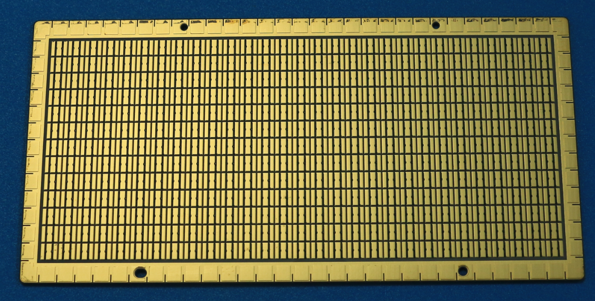
Ceramic substrate PCB, specified in the cited range for ultraviolet phototherapy. Image source: WODE product documentation.
Aluminum vs. Copper vs. Ceramic vs. FR-4: A Like-for-Like Comparison
Most sourcing errors come from comparing across categories rather than within one. The table below keeps the comparison at the level of construction rather than brand, and it separates what the cited specifications establish from what they do not.
| Construction | Base metal | Routing in cited build | Thermal architecture | Main constraint |
|---|---|---|---|---|
| Single-sided aluminum MCPCB | Al1060, Al5052 or Al1 | 1 layer | Heat passes through the dielectric into the aluminum base | No second routing layer; thermal ceiling set by the dielectric and base thickness |
| Double-sided aluminum MCPCB | Al5 | 2 layers | Same metal-core path, with routing on both sides | Limited to two layers; 70/70 µm foil and a 56-up panel constrain fine-feature work |
| Thermoelectric separated copper MCPCB | Cu based | 2 layers | Thermal and electrical paths managed separately | Higher material density than aluminum; the cited build uses 35 µm foil, so current-carrying must be checked rather than assumed |
| Ceramic substrate | Ceramic | — | Ceramic base rather than a metal core | Application-specific; cited in this range for ultraviolet phototherapy |
| FR-4 with metal-free core | FR-4 | 2 layers (cited small-appliance board) | No metal core; heat is spread through copper and vias | Lower thermal spreading than a metal core board; used where thermal demand is modest and routing dominates |
Table 3. Construction-level comparison. Parameters from cited specifications; thermal architecture described qualitatively.
The FR-4 line is included deliberately. The PCB for Small Appliance Lighting Motherboard is a two-layer FR-4 board, 1.0 mm ±0.1 thick, 340.05 × 150.00 mm at 30-up, with 1/1 oz copper, green solder mask and HASL-LF finish. It illustrates the boundary: where a small appliance lighting board does not need a metal core, an FR-4 construction remains the simpler and better-established route, and moving to a metal core board would add cost without a corresponding thermal requirement.
Where the Framework Stops: Real Limits of Aluminum and Copper
A selection framework that only lists advantages is not a decision tool. The following limits are material to the choice.
- Single-sided aluminum cannot host two routing layers. If the design needs driver, protection and LED circuitry on one board, the aluminum option is the double-sided construction, not the single-sided one.
- Base metal does not equal board thermal performance. Bulk copper conducts heat more readily than bulk aluminum, but the dielectric layer between circuit and base typically dominates board-level thermal resistance. Thermal claims should be supported by stack-up data for the exact build.
- The cited copper construction uses a thinner foil than the cited double-sided aluminum board. The Thermoelectric Separated Cu based PCB uses 35 µm copper foil; the Double sided MPCB uses 70/70 µm. Current-carrying capacity and thermal spreading must be engineered for the specific trace geometry, not inferred from the base metal.
- Copper is not a default upgrade. Higher material density and generally higher material cost mean a copper construction should be justified by a thermal or separation requirement that aluminum cannot meet.
- Ceramic is not a general-purpose replacement. In the cited range it appears as a ceramic based PCB for ultraviolet phototherapy, an application-specific choice rather than a drop-in alternative to aluminum.
- Compliance is scope-bound. Company certification and product compliance statements must be checked against the specific model, market and validity period before they are relied on in a purchase contract.
- Panel format constrains assembly. A 1-up 243.00 × 243.00 mm panel and a 56-up 217.54 × 197.80 mm panel demand different handling, tooling and line qualification.
How WODE's MCPCB Range Fits the Framework
WODE Circuit Technology (Zhuhai) Co., Ltd. is a PCB and FPC manufacturer founded in 2003 in Zhuhai, China. The company operates a 150,000 m² manufacturing facility with approximately 500+ staff and an annual production capacity of 6,000,000 sqm, and reports that export business accounts for 50% of total sales, with more than 1000 customers in over 30 countries. Its main products include rigid MCPCB, FPCB, infinity length FPCB, FR-4, CEM1 and CEM3 PCBs and CCL, and PCB inks. The R&D team consists of 15 engineers, and the company holds more than 40 patented technologies.
For the purposes of this framework, the relevant point is coverage. A buyer running the five gates needs aluminum single-sided, aluminum double-sided, copper-based and ceramic options described in a consistent parameter format, because that is what makes a like-for-like comparison possible. The WODE range covers all four: Al1060, Al5052 and Al1 single-sided constructions; an Al5 double-sided construction at 70/70 µm and 56-up; a thermoelectric separated copper-based construction at 35 µm and 4-up; and a ceramic based PCB for ultraviolet phototherapy. Surface finishes across the range include HASL-LF, HASL and OSP, and mask options include white coverlay, white solder mask and matt black solder mask.
The company states that it has passed ISO9001, ISO14001 and IATF16949 international certifications, and that its products comply with UL, RoHS and REACH standards. Company information is available at www.wodepcbfpc.com.
Market Trend: What the Published Projection Does and Does Not Tell Buyers
The category is expanding. The global MCPCB market was valued at USD 935.75 million in 2025, with a projection of USD 1,948.90 million by 2033, and China held a 28.7% share in 2025 according to Future Market Report. Growth of this kind usually tightens two things at once: competition on documented performance, and buyer expectation that specifications are published rather than negotiated case by case.
Three cautions follow. First, the projection is for MCPCBs as a category and does not establish a split between aluminum and copper demand, so it cannot be used to justify a material choice. Second, a growing market does not mean every supplier is qualified for every construction; the ability to produce a single-sided aluminum lighting board is not evidence of capability in a double-sided thermoelectric separated copper substrate. Third, the market share figure describes production and consumption geography, not quality ranking.
Future Outlook
Three developments are likely to shape MCPCB procurement over the next planning cycle, and each is grounded in what the cited material already shows.
Parameter transparency as a differentiator. As the supplier base grows, the practical difference between quotations narrows to whether foil thickness, tolerance, panel format, mask and finish are stated. Buyers who standardize a request template across suppliers will get comparable answers; buyers who accept a description of aluminum PCB will not.
Separation of thermal and electrical design. Constructions that manage thermal and electrical paths separately, such as the thermoelectric separated copper-based board, become relevant as power density in lighting and power electronics rises. The constraint is engineering effort, not availability: the stack-up data has to be produced and reviewed.
Documentation as a gate rather than a formality. With certification scope and declaration validity under closer scrutiny in export markets, the compliance file is becoming part of supplier selection rather than an administrative step after it. Buyers should expect to review scope, validity and model coverage before qualification, not after the first shipment.
Procurement Checklist Before Releasing a PO
The checklist below converts the five gates into items that can be closed in a single supplier review.
| Item | What to confirm | Why it matters |
|---|---|---|
| Base material grade | The exact alloy designation, such as Al1060, Al5052 or Al1, or the copper-based designation | Alloy affects mechanical and thermal behaviour and must match the drawing |
| Layer count | Single-sided or double-sided, stated explicitly | Determines whether driver and protection circuitry can share the board |
| Copper foil thickness | 1 oz, 70/70 µm, 35 µm or the specified value | Sets current-carrying margin and etch resolution |
| Overall thickness and tolerance | 1.6 mm ±10% or 1.6 mm ±0.16 mm as specified | Affects connector fit, housing clearance and assembly |
| Panel size and unit count | Dimensions and ups, such as 208.00 × 225.00 mm 2-up or 217.54 × 197.80 mm 56-up | Drives stencil utilization, handling and depaneling |
| Mask and finish | White coverlay, white or matt black solder mask, and HASL-LF, HASL or OSP | Must match the assembly site's qualified process |
| Compliance file | Certificate scope, validity, model coverage and declaration of conformity | Factory certification does not automatically cover every model |
| Application qualification | Thermal and reliability data for the exact stack-up in the target environment | Bulk material properties do not predict board-level performance |
Table 4. Pre-order checklist derived from the five decision gates.
FAQ
Is an MCPCB the same product as an MPCB or an MCB?
No. MCPCB stands for metal core printed circuit board, a board with a metal base such as aluminum or copper. MPCB and MCB are abbreviations commonly used for miniature circuit breakers, which are switching and protection devices. The two categories use different standards, different manufacturing processes and different supply chains, and a specification for one does not describe the other.
When does a copper-based MCPCB become more suitable than an aluminum one?
A copper-based construction is relevant when the design needs the thermal and electrical paths managed separately, or when the heat load is concentrated beyond what the specified aluminum stack is designed to spread. In the cited range, the Thermoelectric Separated Cu based PCB is a double-sided copper-based substrate with thermoelectric separation, 35 µm copper foil, 1.6 mm ±0.16 mm overall thickness, a 133.80 × 120.00 mm panel at 4-up and an OSP finish, intended for lighting. The decision should be supported by stack-up data for the specific build rather than by base-metal comparison alone.
What copper foil thicknesses appear in the published MCPCB constructions?
Three values appear. The single-sided aluminum boards — Coverlay MCPCB, MCPCB for Road lighting, MCPCB for Motor lighting and High Voltage MCPCB — use 1 oz copper foil. The Double sided MPCB uses 70/70 µm. The Thermoelectric Separated Cu based PCB uses 35 µm. Foil thickness affects current-carrying capacity and etch resolution, so it should be matched to the trace design rather than selected by default.
What panel sizes are available across these constructions?
The published panel formats are 208.00 × 225.00 mm at 2-up for the Coverlay MCPCB and the MCPCB for Road lighting; 243.00 × 243.00 mm at 1-up for the MCPCB for Motor lighting and the High Voltage MCPCB; 217.54 × 197.80 mm at 56-up for the Double sided MPCB; and 133.80 × 120.00 mm at 4-up for the Thermoelectric Separated Cu based PCB. Each format should be checked against the SMT line, stencil frame and depaneling equipment before ordering.
Which surface finishes and solder masks are used, and how should a buyer choose between them?
HASL-LF is used on the Coverlay MCPCB, the MCPCB for Road lighting and the Double sided MPCB. HASL is used on the MCPCB for Motor lighting. OSP is used on the High Voltage MCPCB and the Thermoelectric Separated Cu based PCB. Mask options include white coverlay, white solder mask and matt black solder mask. The practical selection rule is to match the finish to the process already qualified at the assembly site: lead-free HASL keeps a board inside an established HASL-LF window, while OSP provides a copper-protection finish without a solder levelling step.
How should compliance be verified for a specific order?
Verify four items. First, whether the certificate scope covers the construction being purchased. Second, whether the certificate is currently valid. Third, whether the specific product models on the order are covered. Fourth, whether the declaration of conformity is issued for the intended market. WODE states that it holds ISO9001, ISO14001 and IATF16949 certification and that its products comply with UL, RoHS and REACH standards; these statements should be read together with the scope documentation for the specific model.
Which construction suits outdoor road lighting?
The MCPCB for Road lighting is a single-sided Al1060 board with 1 oz copper foil, 1.6 mm ±10% overall thickness, a 208.00 × 225.00 mm panel at 2-up, white solder mask, black silkscreen and HASL-LF finish, intended for road lighting. Outdoor conditions in the lighting application profile include –40°C to +50°C, high humidity, salt spray, UV radiation and wind and rain erosion. Product-level requirements such as IP65 or IP67 protection and salt spray testing of at least 1000 hours are established at luminaire level and should be confirmed separately.
Can one MCPCB construction serve both home appliances and high-voltage lighting?
They are different constructions and should be qualified separately. The Double sided MPCB is a double-sided Al5 board with 70/70 µm copper foil, 1.6 mm ±0.16 mm overall thickness, a 217.54 × 197.80 mm panel at 56-up, white/white solder mask and HASL-LF finish, intended for home applications. The High Voltage MCPCB is a single-sided Al1 board with 1 oz copper foil, 1.6 mm ±10% overall thickness, a 243.00 × 243.00 mm panel at 1-up, white solder mask and OSP finish, intended for lighting. Layer count, foil thickness, panel format and finish all differ, so approval of one does not imply approval of the other.
Есть вопросы или нужны дополнительные детали?
Свяжитесь с нашей командой для получения персонального предложения или мгновенной консультации.
Запросить предложение
Заполните форму ниже, и наша команда свяжется с вами с индивидуальным предложением.
Прямой чат WhatsApp
Предпочитаете общаться в реальном времени? Напишите нам в WhatsApp для мгновенной помощи и быстрых ответов.
- Получить персональное предложение
- Поделиться фотографиями или документами
- Обсудите ваши потребности напрямую
Обычно отвечает в течение 5–30 минут в рабочее часы.