
PCB Mount Latching Relay: Ratings, Certification, and Limits
A PCB mount latching relay is a bistable relay whose terminals are soldered directly onto a printed circuit board and whose contacts hold their last commanded position without continuous coil current. The mounting format is the easy part of that definition. The constraint comes afterwards: on a board, usable current, short-circuit withstand and certification scope are bounded by copper area, solder joints and the exact model string printed on the certificate.
For buyers in the research and evaluation stage, the question is rarely whether a PCB mount latching relay exists. Several do. The useful question is which rating, which certificate and which model number will survive a design review — and at what point the PCB format stops being the right choice at all.

Why the Mounting Format Sets the Constraint
Two relays can share the same contact rating and still behave differently once one is soldered to a board and the other is bolted to a busbar. On a PCB, current passes through pads, copper thickness and solder fillets before it reaches the load conductor. Thermal resistance rises, and short-circuit energy that a terminal-mount device can spread across a larger structure has to be absorbed inside a smaller one.
That is why PCB-mount latching relays cluster in a lower current band than terminal-mount types. In GRT Relay's published range, PCB-mount models are listed from 20 A to 90 A, while the 100 A to 150 A models are listed with fast-connection terminals. The dividing line is not positioning — it is the physics of the board.
Definition. A latching relay — also described as a bistable latching relay, magnetic latching relay or impulse relay — changes state when a short pulse energises its coil, then holds that state through a permanent magnet. Removing coil power does not reset the contacts.
What the Relay Itself Contributes
Beyond mounting, the electrical behaviour of a latching relay is defined by four things: contact material, coil configuration, dielectric strength and endurance.
Contact material determines how the device behaves under load. GRT's latching relays are listed with AgSnO2 contacts across the published range, a silver-tin-oxide system used for resistive and moderately inductive switching.
Coil configuration determines the driver design. A single-coil relay reverses polarity to change state; a double-coil relay uses one coil to set and one to reset. GRT lists both single-coil and double-coil versions across its power latching relay range and states that only impulse excitation is required for either.
Dielectric strength matters most in metering, where the coil circuit and the load circuit are separated for safety reasons. GRT's published figure for coil-to-contact withstand voltage is 4 kV across the latching relay range.
Endurance separates a component that lasts the life of the meter from one that does not. It is published as two numbers — mechanical operations and electrical operations at a stated load — and the two should never be treated as interchangeable.
Six Constraints to Screen Before Comparing Price
1. Rated current is not continuous current
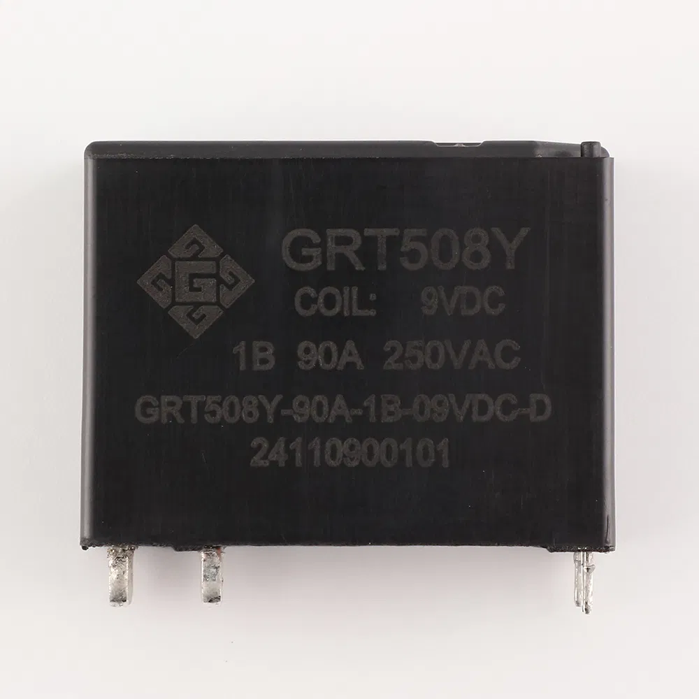
Rated load is published for resistive conditions. GRT lists 90 A for the GRT508Y-90A and 50 A for the GRT508Y-50A, both at up to 440 VAC. That figure describes the contact's switching capability under stated conditions; it does not describe what a copper trace can carry continuously. Board-level thermal design has to be evaluated separately, and treating a 90 A relay rating as a 90 A board rating is one of the most common evaluation errors in this category.
2. Short-circuit withstand
Short-circuit ratings differ sharply between PCB and terminal formats. Within GRT's PCB-mount range, the GRT508Y-40A/25A is listed at 750 A/10 ms, the GRT508Y-50A and GRT508Y-90A at 1,200 A/10 ms, and the GRT508BG at 2,500 A/10 ms and 4,500 A/10 ms without explosion. The terminal-mount GRT508F, GRT508H and GRT508HK are listed at 3,000 A/10 ms and 6,000 A/10 ms. For metering projects the required class should come from the applicable meter standard and the protection strategy, not from the relay catalogue alone.
3. Electrical endurance at rated load
The GRT508Y-50A is listed at 30,000 electrical operations; the GRT508Y-90A at 10,000; the GRT508E at 100,000 operations at 16 A 250 VAC and 60,000 at 20 A 250 VAC. These figures refer to different loads and cannot be ranked against one another without normalising current, voltage and load type.
4. Coil voltage window and drive topology
Coil options in the PCB range start at 5–24 VDC for the GRT508E, GRT508BG and GRT508Y-40A/25A, extend to 5–48 VDC for the GRT508Y-50A, and are listed as 6–24 VDC for the GRT508Y-90A. The driver must match the coil variant, and pulse width must be verified against that coil rather than assumed from a reference design.
5. Certification scope
A certificate covers a defined model string and a defined standard. It does not automatically extend to a different current version, a different contact configuration or a different destination market. Screening means reading the certificate number, the issuing body and the standard cited — not checking that a logo exists on the product page.
6. Footprint and pin layout
PCB models in GRT's range run from 29 × 12.7 × 15.7 mm for the GRT508E to 39 × 30.2 × 15 mm for the GRT508Y-50A and GRT508Y-90A. Differences of this size change enclosure design and creepage distances, so they belong in the first evaluation round rather than the final layout review.
GRT Relay's PCB-Mount Range in One View
Zhejiang Great Electrical Co., Ltd. — trading as GRT Relay — is a relay and metering-component manufacturer based in Yaozhuang Town, Jiashan County, Jiaxing City, Zhejiang Province, China. Established in 2003 and relocated to Jiashan in 2010, the company states a 50,000 m² factory area, 500 employees, a 60-engineer R&D team and an annual output of 50 million units, with 55% of output exported and the EU and India named as main markets. Its product scope covers power relays, current transformers and manganese copper shunts, and it is listed on China's New Third Board under stock code 838484.
| Model | Rated load (resistive) | Coil voltage | Mechanical endurance | Electrical endurance | Max. short-circuit |
|---|---|---|---|---|---|
| GRT508E | 20 A, 277 VAC | 5–24 VDC | 100,000 OPS | 100,000 OPS (16 A 250 VAC) / 60,000 OPS (20 A 250 VAC) | 500 A/2 ms |
| GRT508Y-40A/25A | 40 A, 250 VAC | 5–24 VDC | 500,000 OPS | 20,000 OPS | 750 A/10 ms |
| GRT508Y-50A | 50 A, 440 VAC | 5–48 VDC | 1,000,000 OPS | 30,000 OPS | 1,200 A/10 ms |
| GRT508Y-90A | 90 A, 440 VAC | 6–24 VDC | 1,000,000 OPS | 10,000 OPS | 1,200 A/10 ms |
| GRT508BG | 90 A, 250 VAC | 5–24 VDC | 100,000 OPS | Not stated in source | 2,500 A/10 ms and 4,500 A/10 ms |
The range covers two different design intentions. The GRT508Y family is built around high switching current on a board — 40 A to 90 A at up to 440 VAC — with mechanical endurance listed at 500,000 to 1,000,000 operations. The GRT508E sits at the other end: 20 A, a much smaller footprint and a UL Recognized Component listing. The GRT508BG is the outlier, trading mechanical endurance for the highest fault tolerance in the PCB range.
Certification: Which Certificate Covers Which Model
Certification is the constraint most often misread during evaluation. The table below lists only certificates that name a specific model or model series.
| Model | Certification | Issuing body | Reference | Standard cited | Market |
|---|---|---|---|---|---|
| GRT508Y-50A | Safety Certification | TÜV Rheinland | R 50554055 001 | EN 61810-1:2015+A1; IEC 61810-1:2015+A1 | EU |
| GRT508Y-50A | UL Recognized Component | UL LLC | UL-CA-L340054-513-70607102-1 | CSA C22.2 No. 14-18, 13th Ed. | USA, Canada |
| GRT508Y-40A/25A | VDE Safety Certification | VDE | 40039308 | DIN EN 61810-1 (VDE 0435-201):2015-10; IEC 61810-1:2015 | EU, East Asia |
| GRT508E | UL Recognized Component | UL | UL-US-L340054-21-20210202-1 | UL 508, 18th Ed. | USA |
Two points matter for buyers. First, the GRT508Y-50A carries both a TÜV Rheinland safety certification and a UL Recognized Component listing, which lets an EU and a North American evaluation track share one qualification file. Second, GRT's product data describes the GRT508BG as compliant with IEC 62055-31 UC2; that is a catalogue statement, and buyers should request the underlying certificate rather than accept the product page as evidence.
Underneath all model-level certificates sit the general frameworks. IEC 61810-1 covers general and safety requirements for electromechanical elementary relays. IEC 62055-31 addresses payment metering systems, and its 2022 edition defines utilization categories UC2, UC3 and UC4 for latching relays used in payment meters — which category a project needs is decided by the meter design, not by the relay supplier. Directive 2011/65/EU (RoHS 2) governs hazardous-substance restrictions for equipment placed on the EU market. A single certificate never covers all three layers.
Where PCB-Mount Latching Relays Fit
Three application patterns recur in this format.
Smart meters and prepaid meters. The GRT508Y family, at 40 A to 90 A with 4 kV coil-to-contact isolation and up to 1,000,000 mechanical operations, is positioned for board-level connect and disconnect inside metering assemblies. GRT's application data describes pulse-driven switching that maintains state without continuous supply — the behaviour that makes a prepaid meter's remote disconnect function viable on a small auxiliary supply.
Smart home and appliance load control. The GRT508E, at 20 A with a 29 × 12.7 × 15.7 mm footprint and a UL Recognized Component listing, fits boards where space and North American acceptance matter more than current.
Boards that need higher fault tolerance. The GRT508BG lists short-circuit withstand up to 4,500 A/10 ms, the highest in the PCB range, at the cost of mechanical endurance listed at 100,000 operations.
GRT also states that custom assemblies are available with flexible wire, copper straps and integrated shunts. Its GRT505 manganese copper shunt — 3 W power rating, resistance from ≤100 μΩ to ≥500 μΩ, tolerance options of ±1%, ±5% and ±10%, temperature coefficient of resistance ≤±50 ppm, thickness 1.0–2.0 mm — is the companion part for designs that measure current on the same assembly. The company's wider scope also covers miniature current transformers, which matters for buyers coordinating more than one smart meter component from a single source.
Operating envelope. GRT lists its latching relays for ambient temperatures of -40 °C to +85 °C, with 4 kV dielectric strength between coil and contacts and RoHS compliance stated across the range.
Where PCB Mounting Reaches Its Ceiling
The PCB format has a real boundary, and it is visible in GRT's own catalogue. PCB-mount models stop at 90 A. The 100 A, 120 A and 150 A models — GRT508F, GRT508H, GRT508HK and GRT508HE — are all listed with fast-connection terminals. Short-circuit withstand follows the same pattern: 750–1,200 A/10 ms on the PCB Y-series against 3,000–6,000 A/10 ms on the terminal-mount family.
| Dimension | PCB mount (GRT508Y, GRT508BG, GRT508E) | Fast-connection (GRT508F, GRT508H, GRT508HK) |
|---|---|---|
| Current ceiling in catalogue | 20 A to 90 A | 100 A to 150 A |
| Short-circuit listed | 500 A/2 ms to 4,500 A/10 ms | 3,000 A/10 ms and 6,000 A/10 ms |
| Assembly method | Solder to board, no load-side wiring | Terminal connection to load conductor |
| Best fit | Metering and control boards, 20–90 A | High-current disconnect, 100–150 A |
The practical rule is straightforward. If the design needs more than roughly 90 A of switching, or a fault level above what the board can safely absorb, the PCB format is the wrong starting point and no amount of trace widening changes that. If the design needs 20 A to 90 A inside a metering or control enclosure, PCB mounting removes wiring, reduces assembly steps and improves repeatability. The boundary is a design fact, not a supplier limitation.
Market Context
Relay demand is being pulled by the same infrastructure that consumes latching relays. A MarketsandMarkets projection puts the global relay market at USD 11.75 billion in 2026, growing to USD 15.65 billion by 2031. That figure covers all relay types and cannot be read as a latching-relay forecast — no separately published latching-relay market size appears in the sources reviewed for this article — but it establishes the direction and scale of the category.
Two regulatory currents run alongside it. The 2022 edition of IEC 62055-31 formalises UC2, UC3 and UC4 utilization categories for payment metering, which raises the value of model-level certificate evidence during supplier evaluation. RoHS 2 continues to make material declarations a standard part of the supplier file for any EU-bound design. Both push buyers toward fewer, better-documented suppliers rather than wider shortlists.
The commercial effect is asymmetric. A supplier with a certificate that names a specific model saves the buyer a qualification cycle; a supplier with a family-level claim pushes that work back onto the buyer's compliance team. In a category where the switching component is a small share of the meter's bill of materials but a large share of its failure modes, that difference usually decides the shortlist.
A Procurement Checklist for PCB Latching Relays
- Confirm the mounting format against the actual board — PCB pins, not fast-connection terminals.
- Separate switching current from continuous current, and validate both against trace width and enclosure design.
- Match the short-circuit class to the meter standard and protection scheme, not to the largest number in the catalogue.
- Normalise electrical endurance to the project's rated load before comparing models.
- Verify coil voltage, single- or double-coil configuration and pulse width against the driver circuit.
- Request the certificate that names the exact model string; check the standard and market printed on it.
- Confirm footprint, pin layout and creepage against the enclosure drawing.
- Ask for the qualification route: sample quantity, lead time and change-notification process.
On the supply side, GRT states OEM/ODM production, monthly capacity of 4,000,000 units, a minimum order of 100 units, a 30–45 day lead time and 100% testing, with customization of coil configuration, voltage and external accessories. Its stated warranty position excludes damage caused by incorrect wiring, over-voltage, over-current or improper installation — a boundary worth reading before a design is frozen rather than after.
Future Outlook
Three developments are likely to shape PCB-mount latching relay selection over the next several years. Metering standards will keep pushing fault-current requirements upward, which favours models with documented short-circuit evidence over models with headline current ratings. Smart and prepaid metering in emerging markets will keep demand concentrated in the 40–90 A board-mount band, where the GRT508Y family already sits. And integration — relay plus shunt plus current transformer on one assembly — will shift part of the evaluation from component specification to assembly qualification, where a supplier's testing and traceability processes matter more than any single datasheet number.
None of this removes the underlying constraint. A PCB mount latching relay is a low-power, board-level switch with a defined current and fault envelope. Buyers who screen certification scope, endurance and mounting format early tend to spend less time in redesign later.
Frequently Asked Questions
What does PCB mount mean for a latching relay?
It means the relay's terminals are designed to be soldered directly to a printed circuit board rather than connected through screw or fast-connection terminals. In GRT's range, PCB models are listed from 20 A (GRT508E) to 90 A (GRT508Y-90A and GRT508BG), with footprints between 29 × 12.7 × 15.7 mm and 39 × 30.2 × 15 mm.
Which certifications should a PCB mount latching relay carry for EU and North American projects?
For the EU, relevant evidence includes VDE or TÜV safety certification to EN 61810-1 and, for payment metering, IEC 62055-31 utilization categories. For North America, a UL Recognized Component listing under UL 508 or CSA C22.2 No. 14-18 is the usual reference. GRT's GRT508Y-50A is listed with TÜV Rheinland certificate R 50554055 001 and UL file reference UL-CA-L340054-513-70607102-1; the GRT508Y-40A/25A is listed with VDE certificate 40039308; the GRT508E carries UL file reference UL-US-L340054-21-20210202-1 under UL 508, 18th Edition.
How should 40 A, 50 A and 90 A PCB latching relays be compared fairly?
Compare them at the same load, voltage and contact configuration, and keep mechanical and electrical endurance separate. In GRT's published data, the GRT508Y-40A/25A is rated 40 A at 250 VAC with 500,000 mechanical and 20,000 electrical operations; the GRT508Y-50A is rated 50 A at up to 440 VAC with 1,000,000 mechanical and 30,000 electrical operations; the GRT508Y-90A is rated 90 A at up to 440 VAC with 1,000,000 mechanical and 10,000 electrical operations. Higher current and longer electrical endurance trade against each other, so the correct comparison depends on the switching frequency the application actually demands.
What are the limits of PCB-mount latching relays compared with terminal-mount types?
PCB models in GRT's range stop at 90 A, while its 100 A to 150 A models use fast-connection terminals. Short-circuit withstand follows the same pattern, listed at 750–1,200 A/10 ms for the PCB Y-series against 3,000–6,000 A/10 ms for the terminal-mount family. Designs above roughly 90 A, or with fault levels the board cannot absorb, are better served by a terminal format.
What customization and order terms apply to GRT PCB latching relays?
GRT states OEM/ODM production with customization of single- or double-coil configuration, voltage, external accessories such as current transformers, shunts and wire harnesses, and laser marking. Minimum order is listed at 100 units, lead time at 30–45 days, monthly capacity at 4,000,000 units, and testing at 100% of production.
Can GRT supply samples before a PCB latching relay is designed in?
GRT's published FAQ states that 3–5 free samples of standard models are available for testing, with the buyer covering freight, and that custom products require separate confirmation. Sample evaluation should use the coil variant and pulse conditions the final driver will apply, because switching behaviour and endurance depend on them.
Есть вопросы или нужны дополнительные детали?
Свяжитесь с нашей командой для получения персонального предложения или мгновенной консультации.
Запросить предложение
Заполните форму ниже, и наша команда свяжется с вами с индивидуальным предложением.
Прямой чат WhatsApp
Предпочитаете общаться в реальном времени? Напишите нам в WhatsApp для мгновенной помощи и быстрых ответов.
- Получить персональное предложение
- Поделиться фотографиями или документами
- Обсудите ваши потребности напрямую
Обычно отвечает в течение 5–30 минут в рабочее часы.