
PSA vs Membrane Nitrogen Generators: A Buyer's Decision Framework for Flow, Purity, and Footprint
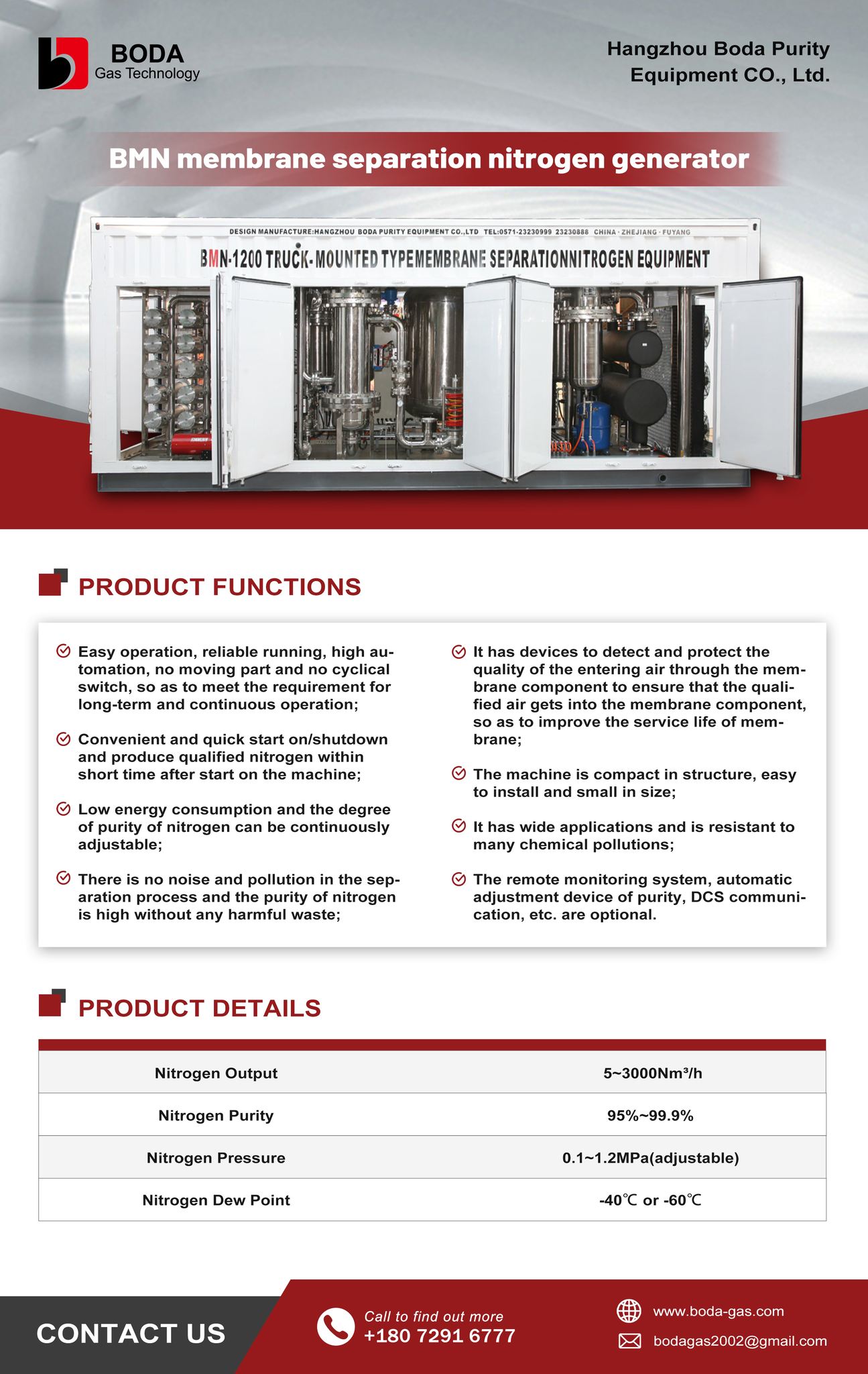
A membrane separation nitrogen generation package such as the BMN Series delivers 5–3,000 Nm³/h at 95–99.9% purity with no moving parts in the separation path — the compact reference point in this comparison.
Most buyers evaluating on-site nitrogen generation are not deciding whether to generate nitrogen. They are deciding which separation technology to install. Feed air is the same input either way. What differs is the purity each route can hold economically, the floor area the package consumes, and the maintenance load it creates over a ten-year horizon.
This framework treats PSA and membrane nitrogen generation as two operating envelopes rather than two competing products. It maps each envelope against three procurement variables — flow and purity, footprint and installation, and feed-air pre-treatment — and then sets out the verification questions that separate a technically sound quotation from a commercially optimistic one.
Where PSA and Membrane Actually Diverge
Both technologies start from clean, dry compressed air and both produce nitrogen on site. The split happens inside the separation stage.
Pressure Swing Adsorption relies on carbon molecular sieves. Under working pressure, the sieve adsorbs oxygen, carbon dioxide and moisture preferentially while nitrogen concentrates in the gas phase. A twin-tower arrangement alternates between adsorption and regeneration so that production is continuous. In the BODA GAS range, the BXN Series PSA nitrogen generator covers a nitrogen flow rate of 1–3000 Nm³/h at 95%–99.999% purity, with outlet pressure adjustable from 0.1 to 1.15 MPa and dew point from −40°C to −70°C.
Membrane separation uses hollow-fibre bundles. Oxygen, water vapour and other fast-permeating gases pass through the membrane wall first and are vented as oxygen-rich gas, while the slower nitrogen is retained and concentrated into a dry nitrogen-rich stream. The BMN Series membrane separation nitrogen generator covers 5–3000 Nm³/h at 95%–99.9% purity, with nitrogen pressure adjustable from 0.1 to 1.2 MPa and a dew point of −40°C or −60°C depending on configuration.
The structural difference matters more than the specification table suggests. A membrane separation process has no moving parts in the separation path, which is why manufacturers describe low maintenance requirements and reliable operation in high-vibration areas. A PSA system cycles valves continuously, which introduces wear items — and, more importantly, introduces a dependency on feed-air quality that determines whether the carbon molecular sieve reaches year eight or fails in year three.
The practical read: membrane wins on simplicity and floor space in the 95–99.5% band. PSA is the only realistic route above 99.5%, and it is the sole option when the process needs trace-level oxygen and carbon dioxide control.
Variable One — Flow Rate and the Purity Curve
Flow capacity alone rarely decides the question. Both technologies reach the 3,000 Nm³/h class. What decides it is the shape of the flow-versus-purity curve.
Membrane systems are most economical between 95% and 99.5% purity. The BMN Series lets operators set the specific purity the application requires, and that setting is the primary energy control — compressed air that is not spent chasing unneeded purity is compressed air that is not paid for twice. The ceiling is real, though. Above 99.5%, membrane efficiency falls away sharply, and PSA becomes the more efficient choice.
PSA covers the higher bands. The BXN Series reaches 99.999%. Where a process needs tighter control over trace contaminants, the BCP Series carbon loaded purification nitrogen generator pushes purity to ≥99.9995% while holding oxygen at ≤5 ppm, carbon dioxide at ≤1 ppm and dew point at ≤−60°C. That is a different class of gas from anything a membrane module produces.
A workable purity banding reference, drawn from BODA GAS application data:
| Purity band | Typical applications | Technology fit |
|---|---|---|
| 95%–98% | Fire prevention, marine tank blanketing, oil-field pipeline purging, general tyre inflation | Membrane or PSA |
| 99%–99.9% | Modified atmosphere packaging, winemaking, conventional plastics processing, tank blanketing | Membrane or PSA |
| 99.95%–99.99% | Mild-steel laser cutting, electronics manufacturing, cable production, pharmaceutical blanketing | PSA |
| 99.999% and above | Titanium alloy and special-metal cutting, high-end electronics, specialist laboratory work | PSA with purification stage |
The procurement consequence is straightforward. If the required purity sits in the top two bands, membrane drops out of the shortlist. If it sits at or below 99.5%, then flow rate, capital cost and available floor area become the real comparison — not purity.
Market structure supports this reading without proving it. According to Fortune Business Insights (2024), PSA technology accounts for approximately 48% of global nitrogen generator market share, making it the dominant technology segment. That figure reflects the weight of higher-purity and larger-capacity industrial demand rather than a blanket performance advantage.
Variable Two — Purity Alone Is Not the Specification
A purity percentage describes the nitrogen fraction. It says nothing about what the remaining fraction contains. Buyers running processes sensitive to oxygen or carbon dioxide need the contaminant list, not the headline number.
For the BCP Series that list is explicit: oxygen content ≤5 ppm, carbon dioxide content ≤1 ppm, dew point ≤−60°C. These are the figures that matter for lithium-ion electrode drying, electrolyte blanketing, semiconductor wafer purging and photovoltaic cell sintering.
The carbon-loaded purification route also has a structural advantage worth noting: because it does not contain hydrogen, it suits applications with strict requirements around both hydrogen and oxygen. Hydrogenation purification systems such as the BHP Series address a different requirement profile and should be evaluated against the specific project conditions rather than substituted by default.
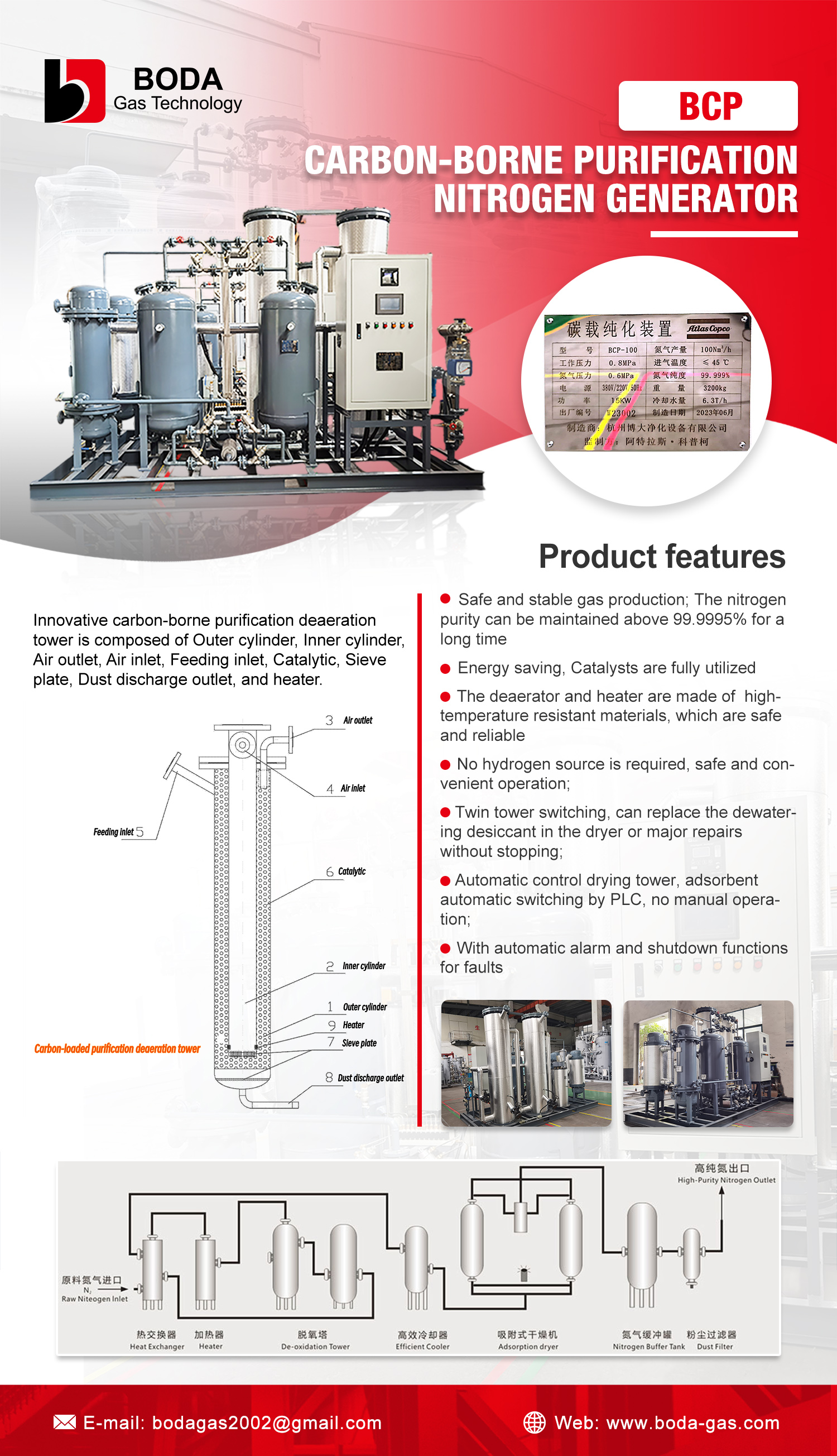
BCP Series carbon loaded purification nitrogen generator: ≥99.9995% purity, O₂ ≤5 ppm, CO₂ ≤1 ppm, dew point ≤−60°C.
Membrane systems handle contamination differently. They have no regenerating bed to protect, and the product gas is inherently dry because the separation process does not cycle moisture through an adsorbent. What they cannot do is drive oxygen down to the ppm range. If the process tolerance for oxygen is measured in single-digit ppm, that single fact settles the technology choice.
For food-grade nitrogen there is one compliance point that applies regardless of technology. EIGA standards require at least one continuously online residual oxygen analyser in the nitrogen gas stream. Online oxygen analysis and automatic venting of out-of-specification gas should appear in the purchase specification as standard, not as an optional item to be added later.
Variable Three — Footprint, Noise and Installation Layout
The BMN Series occupies little space and runs quietly enough to be installed directly on the production floor. That is a genuine advantage in plants where the gas system competes with process equipment for floor area. Membrane modules are compact, and there is no need to reserve the vertical clearance that twin adsorption towers, valve trains and regeneration pipework require.
PSA footprint depends entirely on configuration. The BXN Series is available as an industrial PSA nitrogen generator, a skid-mounted PSA nitrogen generation package, a movable containerised PSA nitrogen generator, an ASME-standard nitrogen generator and a stainless steel nitrogen generator. Skid and container formats solve the site problem by moving fabrication and testing into the factory — the package arrives assembled and tested, and installation reduces to positioning and connecting power.
Noise is a planning input rather than a specification detail. The BXN Series is rated at 65–85 dB(A). Projects should either allocate a dedicated plant room or design acoustic treatment and unit placement during the layout stage.
One element is routinely under-planned: buffer capacity. A nitrogen system normally includes a wet air buffer tank, a dry air buffer tank and a nitrogen buffer tank, each performing a different function. The air buffer tank stabilises compressed-air pressure, reserves air volume and reduces pressure impact. The dry air buffer tank maintains a stable dry-air supply to the PSA towers against peak-demand pressure drop. The nitrogen buffer tank smooths the pressure and flow fluctuation caused by tower switching, maintaining stable nitrogen quality while meeting peak gas consumption. All three occupy floor area and should be drawn into the layout from the start.
Feed-Air Pre-Treatment: The Decision Matrix
Feed air is the one input PSA and membrane systems share, and it is the hidden cause of most performance complaints in the field. Carbon molecular sieve poisoning and membrane fouling both trace back to air quality upstream of the separation stage. The table below maps end-point requirements to the equipment that satisfies them.
| Equipment | Model | Rated flow | Key output | Stage in system |
|---|---|---|---|---|
| High efficiency oil-water separator | FYS Series | 1–500 Nm³/min | Gas-liquid separation efficiency >98%, pressure loss ≤0.02 MPa | First-stage bulk liquid and oil droplet removal |
| Refrigeration dryer | FAD Series | 1–200 Nm³/min | Dew point ≤−23°C under ambient pressure | Baseline moisture removal |
| Heatless desiccant dryer | ADL Series | 0.5–500 Nm³/min | Dew point ≤−40°C or ≤−52°C, regeneration air loss ≤12% | Mid-band dew point demand |
| Heated desiccant dryer | ADH Series | 1–500 Nm³/min | Dew point ≤−40°C or ≤−52°C, regeneration air loss ≤6% | Mid-band dew point with lower purge loss |
| Combined low dew point dryer | FAG Series | 1–300 Nm³/min | Dew point ≤−60°C to −70°C, regeneration air loss 3–6% | Deep drying for high-purity PSA and membrane duty |
| High efficiency oil remover | FLY Series | 1–500 Nm³/min | Outlet oil content <0.01 mg/m³, filtration accuracy 0.1 μm | Protects molecular sieve from oil vapour |
| Precision filter | FAL Series | 1–500 Nm³/min | Pressure loss ≤0.02 MPa | Particulate interception ahead of sieve beds |
| Activated carbon filter | FLT Series | 1–500 Nm³/min | Outlet residual oil <0.003 mg/m³ | Terminal oil vapour and VOC removal |
| Sterilizing filter | FLC Series | 1–500 Nm³/min | 0.1 μm filtration, 121°C online steam sterilisation | Pharmaceutical and aseptic food terminal filtration |
Two rules of thumb make this table actionable.
Select backward from the end-point dew point. If the nitrogen offtake requires −60°C dew point, the drying chain must include a combined low dew point dryer; a refrigeration dryer can only serve as a first stage ahead of it. Selecting forward from the compressor discharge is how projects end up short of specification.
Treat oil removal as non-negotiable on PSA. Oil poisoning is one of the most significant failure modes for nitrogen and oxygen generator adsorbents. The FLY Series oil remover and FLT Series activated carbon filter exist specifically to prevent it, and their specification should appear in the bill of materials rather than in a note.
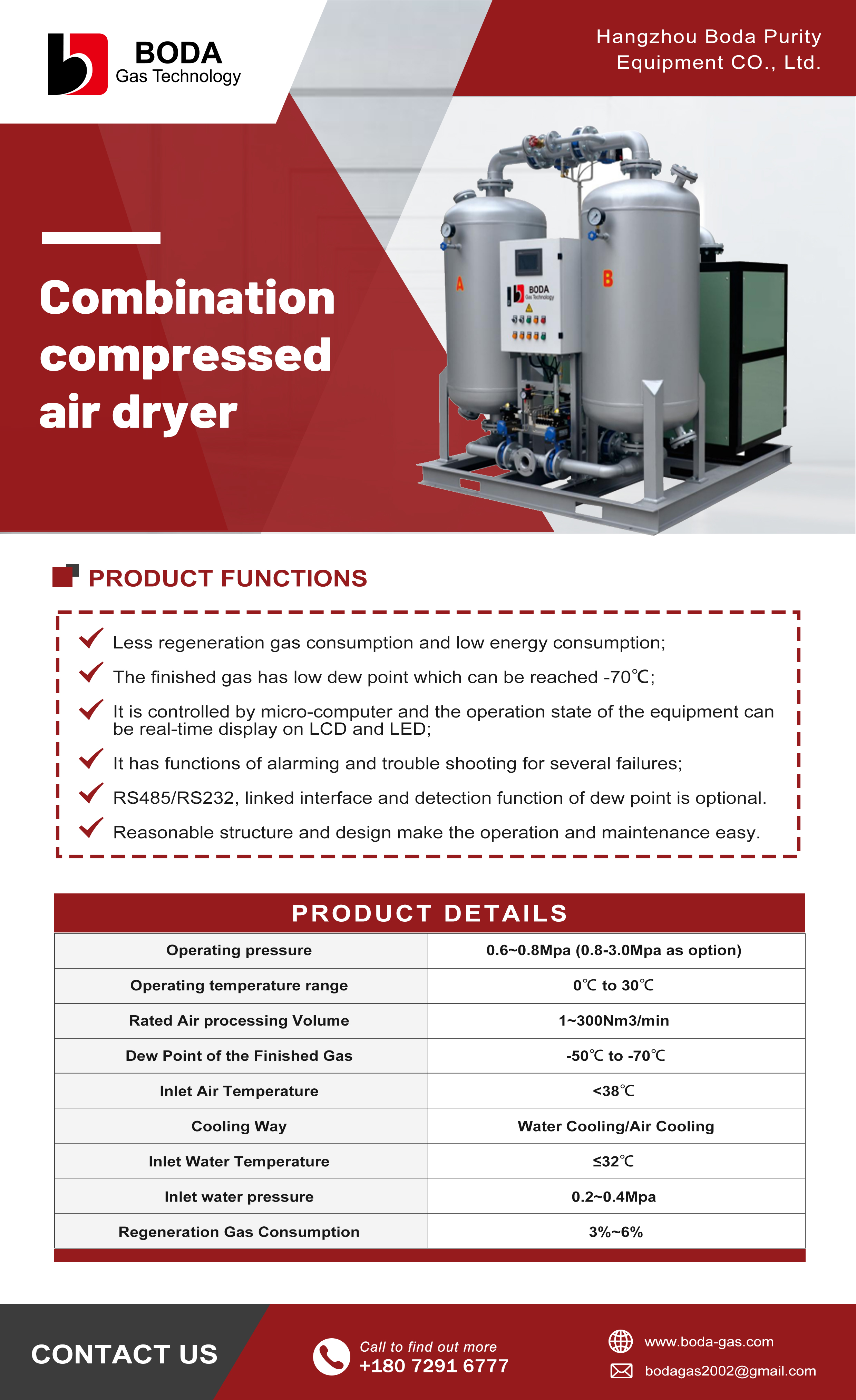
FAG Series combined low dew point compressed air dryer: −60°C to −70°C dew point, 3–6% regeneration air loss.
Two further inputs are persistently underestimated. First, ambient temperature: where the customer site runs hot, or where the offtake point carries a defined water-content or dew-point requirement, a dryer stops being optional and becomes a mandatory system element. Second, buffer volume: peak-consumption duty in tyre inflation, laser cutting and plasma cutting demands buffering sized for the peak rather than the average — a decision that has to be made at layout, not at commissioning.
Verifying Maintenance and Operating Cost Claims
Maintenance discussions often stop at the phrase "routine servicing." The intervals below are specific enough to be checked line by line against a supplier quotation.
| Maintenance item | Reference interval |
|---|---|
| Air compressor service — oil, oil filter, air/oil separator | Every 3,000–4,000 running hours |
| Precision filter element replacement | Every 8,000 hours |
| Air dryer desiccant replacement | Generally 16,000–24,000 hours |
| Carbon molecular sieve replacement | 6–10 years |
The carbon molecular sieve replacement interval carries the greatest weight in a total-cost model, because it spans years rather than hours. That makes the important procurement question not "how often is the sieve replaced" but "what causes it to be replaced early." The answer points upstream, to oil vapour and liquid water. Membrane elements are not exposed to the same adsorbent-bed failure mode, but they have their own performance-decay characteristics — which makes spare-part availability and whole-life supplier support a legitimate comparison criterion for both routes.
On running cost, a widely cited industry reference point is that on-site nitrogen generation can reduce nitrogen supply costs by up to 40% compared with traditional cylinder deliveries, mainly by eliminating logistics. The actual figure depends on local delivery costs, consumption pattern and operating hours. It is a direction to model before purchase, not a committed saving.
Installation Layout: What the Package Actually Needs
Installation effort depends more on pre-delivery planning than on the equipment itself. Skid-mounted and containerised packages move assembly and testing into the factory, so site work reduces to positioning and connecting the power cable — the unit is designed as plug-and-play after power-on.
Some conditions need separate assessment rather than assumption. Hazardous-area installations in Zone 1 or Zone 2 gas environments require explosion-proof construction. Projects in the European Union require pressure vessels to comply with the Pressure Equipment Directive (PED 2014/68/EU) and to carry the CE mark. Chemical industry deployments frequently specify ASME construction and stainless steel pipework. Each of these raises manufacturing complexity and must be settled at technical proposal stage, not discovered on site.
For continuous duty, redundancy belongs in the project design. The BXN and BMN series are both specified for 24/7 continuous operation, but that addresses equipment availability. Power redundancy and backup gas supply are plant-side decisions that remain with the buyer.
The Pre-Purchase Verification List
Hangzhou Boda Purity Equipment Co., Ltd. (BODA GAS) is a nitrogen and oxygen generation equipment manufacturer established in 2002 and headquartered in Hangzhou, Zhejiang Province, China, producing PSA nitrogen generators, PSA oxygen generators and compressed air purification equipment. The questions below are the ones that consistently separate a complete engineering offer from a trading quotation, and they apply whichever technology is selected.
On flow and purity matching
- At the stated operating conditions of inlet pressure and ambient temperature, what nitrogen flow is actually delivered at the quoted purity?
On pre-treatment
- What dew point is required at the nitrogen offtake, and which dryer in the chain is responsible for achieving it?
- What residual oil content is permitted at the point of use, and are both the oil remover and the activated carbon filter included in the quotation?
On materials and compliance
- Are the pressure vessels built to the standard required in the destination market? For EU installation, PED 2014/68/EU compliance and CE marking are mandatory.
- Is the pipework specified in carbon steel or SS304, and does that choice match the moisture and cleanliness profile of the application?
On lifecycle
- When will the carbon molecular sieve require replacement, and can it be replaced without stopping production? The BCP Series uses a double-tower deaerator structure that allows carbon-loaded catalyst to be added or replaced without shutting down the machine — request written confirmation of the same for any quoted configuration.
- What are the consumable and spare-part prices at the stated service intervals?
On operation
- How is guaranteed outlet purity maintained — is there continuous online oxygen analysis with automatic venting of non-conforming gas?
On installation
- Is the package function-tested before shipment? In the BODA GAS quality process, every unit passes visual inspection and function inspection before release.
Comparison with Established Supply Routes — and the Limits of Each Choice
Both PSA and membrane generation improve on delivered nitrogen, whether cylinders or liquid. The gain is structural: the logistics operation disappears, and supply no longer depends on external gas suppliers or nitrogen market price movement.
Neither technology is free of constraints, and a framework that presents one as universally superior is not useful.
The membrane limitation is a purity ceiling. The 95% to 99.9% band covers modified atmosphere packaging, tyre inflation, pipeline purging and most blanketing duty. Above 99.5%, efficiency falls, and beyond 99.9% the technology is no longer a realistic option. Buyers who might later need to raise purity should treat that as a planning constraint, not a future upgrade.
The PSA limitation is mechanical complexity. It depends on selective pre-treatment, cyclic valve operation, an adsorbent bed and a replacement schedule. It introduces valve noise, and it carries an irreversible failure mode if pre-treatment is neglected. It also demands more floor area and more maintenance line items than a membrane package of equivalent output.
A third constraint applies to both: on-site generation ties gas supply to plant uptime. That is an advantage when the plant runs continuously and a risk exposure when it does not. Projects in rented facilities, at sites with unstable power, or with seasonal demand should model this explicitly.
The selection rule holds: choose the technology whose operating envelope covers the purity the process actually requires, with adequate margin — and do not let that margin drive the decision.
Future Outlook
Third-party forecasts place the global industrial nitrogen generator market at USD 4.29 billion in 2023, projected to reach USD 6.47 billion by 2031 (Verified Market Research). Three structural shifts in that trajectory are relevant to technology selection.
Chemical applications are the fastest-growing segment, at an expected CAGR of 6.0%. Catalyst blanketing, process gas inerting and solvent replacement are duty profiles that combine continuous operation with strict demands on gas composition and pressure stability — the conditions where pre-treatment quality and system control matter most.
Food and beverage held approximately 49.8% of revenue share in 2023, driven largely by modified atmosphere packaging (Grand View Research). That demand concentrates in the 99.0% to 99.9% band, which is the zone where both technologies are technically viable — so decisions in this segment turn on cost, footprint and service rather than on technical reach.
Capacity distribution remains weighted toward smaller installations. PSA nitrogen generator installations break down as sub-100 Nm³/h (42%), 100–500 Nm³/h (36%) and above 500 Nm³/h (22%). Small and mid-scale installations dominate, and those are precisely the projects most sensitive to floor area and upfront investment.
Containerisation is growing faster than the overall market, with the containerised PSA nitrogen generator segment projected at a 7.6% CAGR from 2025 to 2032, driven by remote oil and gas sites (Reliable Research IQ). Containerisation addresses installation location rather than separation technology, but it widens the range of sites where PSA becomes layout-feasible.
Asia-Pacific is the fastest-growing region, projected to hold a 35% share by 2032 (Verified Market Research), which brings shorter lead times and closer service networks to buyers in that region.
For buyers, the technology choice itself is likely to remain stable. What changes is everything around it — the completeness of the pre-treatment chain, the sophistication of monitoring and control, and whether a supplier can integrate these into one coordinated package rather than a set of separate products.
FAQ
How do I decide between a PSA and a membrane nitrogen generator for my application?
Start from the purity the offtake point requires. Membrane separation covers 95% to 99.9% and is most economical below 99.5%; above that, PSA is the more efficient route. In this range, PSA nitrogen generators can reach 99.999% purity using carbon molecular sieves, and purification stages extend that further — the BCP Series carbon loaded purification nitrogen generator reaches ≥99.9995% with oxygen at ≤5 ppm and carbon dioxide at ≤1 ppm. Flow rate then determines package size, and both technologies cover capacities up to 3,000 Nm³/h.
What feed-air pre-treatment does each technology require?
Both require clean, dry air, but the failure modes differ. PSA depends on carbon molecular sieve, which is irreversibly degraded by oil vapour and liquid water, so a typical chain runs oil-water separator, dryer, precision filter, oil remover and activated carbon filter, plus a buffer tank. Where the offtake requires −60°C dew point, a combined low dew point dryer such as the FAG Series is required; a refrigeration dryer alone delivers only around −23°C. Membrane systems benefit from the same upstream filtration but carry no adsorbent bed to poison. Industry practice for food-grade nitrogen adds one further requirement regardless of technology: EIGA standards require at least one continuously online residual oxygen analyser in the nitrogen stream.
How much purity and flow can a membrane system realistically deliver?
The BMN Series membrane separation nitrogen generator is rated at 5–3000 Nm³/h with 95%–99.9% purity, pressure adjustable from 0.1 to 1.2 MPa, and dew point of −40°C or −60°C. Two characteristics are worth noting. Membrane systems have no moving parts in the separation process, which supports reliable operation in high-vibration environments. And because the operator sets the purity the application actually needs, energy consumption tracks that setting rather than a fixed design point. Above 99.5% purity, however, PSA becomes the more efficient choice.
What are the realistic maintenance intervals and consumable costs?
Reference intervals published by BODA GAS are: air compressor service including oil, oil filter and air/oil separator every 3,000–4,000 running hours; precision filter element replacement every 8,000 hours; air dryer desiccant generally 16,000–24,000 hours; and carbon molecular sieve replacement at 6–10 years. The sieve interval dominates whole-life cost, which makes pre-treatment quality — not the sieve specification itself — the decisive variable. Membrane packages remove several of these line items because there is no desiccant or adsorbent bed to service.
How much floor space and installation work should be planned for?
Membrane packages are compact and quiet enough for direct installation on the production floor, with no vertical clearance needed for adsorption towers and valve trains. PSA systems are available as skid-mounted packages, movable containerised units, ASME-standard builds and stainless steel builds; skid and container formats reduce site work to positioning and connecting power, with plug-and-play operation after power-on. Plan for buffer capacity as well: a nitrogen system normally includes a wet air buffer tank, a dry air buffer tank and a nitrogen buffer tank, each occupying floor area. For hazardous areas, explosion-proof construction for Zone 1 and Zone 2 environments is a separate design requirement, and EU installations require pressure vessels to comply with PED 2014/68/EU and carry the CE mark.
For readers who want the full technical specification set behind these figures, the BODA GAS product manual is available for reference and download.