
PWM vs Built-In MPPT in Hybrid Inverter Charging Setups
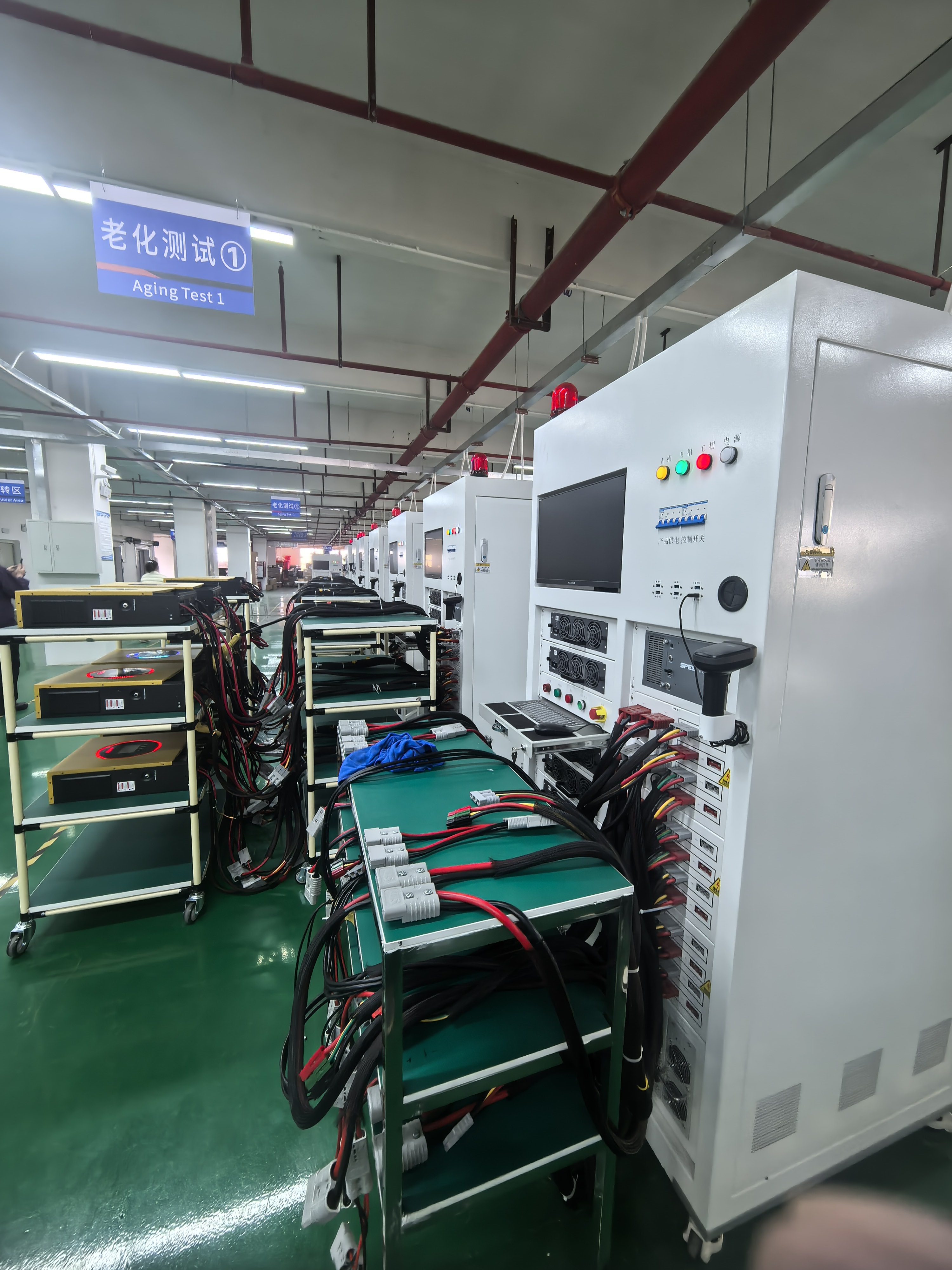
Aging test equipment: published quality-control procedures for this hybrid inverter range include a 100% aging test of 4–8 hours before shipment.
Two charging architectures sit behind most hybrid solar inverter purchases: a separate PWM or MPPT solar charge controller wired alongside an inverter, or a single hybrid inverter with a built-in MPPT charger. This comparison is written from a neutral buyer's viewpoint and uses only published specification data — conversion efficiency of at least 95% for PWM and at least 98% for MPPT, an MPPT operating window of 60–450 VDC, a 500 VDC maximum PV open-circuit voltage, 27 A maximum PV input current, 9000 W maximum PV input power, and a 120 A maximum total charge current from PV and AC.
Why the charging path, not the inverter label, decides the comparison
In a hybrid installation, the charging path determines how much of a PV array's rated output actually reaches the battery. Two systems can carry the same inverter rating and behave very differently once array voltage, cable runs and charging current are taken into account. A separate controller plus a separate inverter uses two enclosures, two wiring runs, two commissioning steps and two warranty files. A hybrid inverter with an integrated MPPT charger collapses that into one enclosure, one PV input and one charge-current ceiling.
For an evaluation-stage buyer, the practical consequence is that the comparison should not start with brand names. It should start with five measurable questions: what PV voltage window does the charger accept; what is the maximum charging current; what conversion efficiency is published for the charging stage; which certificate scope names the exact model; and what purchase terms govern sampling, lead time and acceptance testing. Everything else — enclosure finish, display type, brand recognition — is secondary to those five.
PWM charging: where the ≥95% figure comes from, and where it stops
A PWM (pulse-width modulation) solar charge controller connects the PV array to the battery through switching, and the published specification for PWM controllers in this product family states a conversion efficiency of at least 95%. The same controller specification set lists a battery voltage range of 12 V / 24 V / 48 V with automatic identification, a maximum charging current of 10 A to 200 A depending on model, a maximum PV input power of 130 W to 11,000 W depending on voltage and current, an IP32 indoor protection level, an operating temperature range of −20 °C to +55 °C, and an optional RS485 or Bluetooth communication interface on smart models.
The boundary is structural rather than electronic. PWM charging works by regulating the array down toward battery voltage, so the array's operating voltage must stay compatible with the battery bank. That limits how freely panels can be wired in series, and it means array sizing is effectively voltage-constrained rather than power-optimised. For small, short-cable, low-budget installations the approach remains legitimate — it is simpler and the published efficiency floor of 95% is stated as measured at the controller level — but it leaves array power on the table whenever panel voltage sits well above battery voltage.
What a built-in MPPT charger changes: 60–450 VDC, 27 A, 9000 W, 120 A
MPPT (maximum power point tracking) controllers carry a published conversion efficiency of at least 98% in the same controller specification family — a three-point improvement over the PWM figure. In a hybrid inverter, that MPPT stage is integrated rather than purchased separately. The integrated charger in the SYP hybrid inverter range accepts an MPPT operating voltage of 60–450 VDC, tolerates a maximum PV open-circuit voltage of 500 VDC, draws a maximum PV input current of 27 A, and accepts a maximum PV input power of 9000 W. Its maximum PV charge current is 120 A, its maximum AC charge current is 120 A, and its maximum total charge current from PV and AC combined is also 120 A.
That last figure deserves attention during evaluation. The PV and AC charge currents are not additive: the system ceiling stays at 120 A whether the energy arrives from the array, from the grid or from both at once. Buyers who size battery banks on the assumption that PV and AC charging stack will overestimate the recharge speed available in a cloudy week. The wider 60–450 VDC window, by contrast, is a genuine working advantage over PWM, because longer series strings can be used while staying under the 500 VDC open-circuit limit, which in turn reduces cable current and voltage drop over long array runs.
Side-by-side: PWM controller, MPPT controller, built-in MPPT hybrid inverter
| Decision factor | Separate PWM controller + inverter | Separate MPPT controller + inverter | Hybrid inverter with built-in MPPT |
|---|---|---|---|
| Charging-stage conversion efficiency | ≥95% (published controller spec) | ≥98% (published controller spec) | ≥98% (MPPT charger type) |
| PV input voltage window | Constrained by battery voltage compatibility | Wider window, model dependent | 60–450 VDC operating; 500 VDC max open circuit |
| Maximum charging current | 10 A–200 A, model dependent | 10 A–200 A, model dependent | 120 A PV, 120 A AC, 120 A combined (PV + AC) |
| Maximum PV input power / current | 130 W–11,000 W depending on voltage and current | 130 W–11,000 W depending on voltage and current | 9000 W / 27 A |
| Enclosures and wiring runs | Two devices, two wiring runs | Two devices, two wiring runs | Single device |
| Interfaces | RS485 / Bluetooth optional on smart models | RS485 / Bluetooth optional on smart models | RS232 / RS485 / USB; WiFi optional (internal or external) |
| Protection level | IP32 (indoor) | IP32 (indoor) | IP21 (indoor) |
| Battery types | Lead-acid / lithium, per controller model | Lead-acid / lithium, per controller model | Lithium and lead-acid on the inverter specification |
Figures are taken from published controller and inverter specification data for this product family. Efficiency values describe the charging stage, not whole-system round-trip efficiency.
The built-in option in detail: GOTOSOLAR SYP reference specification
GOTOSOLAR is the brand of FOSHAN SOLARUP TECHNOLOGY CO.,LTD, a Foshan-based manufacturer of hybrid solar inverters and solar charge controllers that also trades as GoToSolar. The company operates three production bases — in Foshan, Yiwu and Yingtan — dedicated to solar charge controllers and hybrid inverters, and publishes an annual controller shipment figure above one million units. For buyers comparing charging architectures, the relevant reference point is the SYP hybrid inverter range, an off-grid inverter type listed in six model designations: SYP1.5KW12V, SYP2.5KW12V, SYP4.0KW24V, SYP6.5KW48V, SYP12.0KW48V and SYP12.0KW48V/P.
Electrical envelope of the 6.5KW/48V configuration
The published parameter sheet for the 6.5KW/48V configuration documents a rated input voltage of 208 / 220 / 230 / 240 VAC on L + N + PE, an input voltage range of 90–280 ±3 VAC in normal mode and 170–280 ±3 VAC in UPS mode, and 50 / 60 Hz auto-adaptive frequency. Rated capacity is 6.5 kW with 12 kVA surge power, power factor 1, pure sine wave output, and a 10 ms transfer time in both normal and UPS mode. Battery-mode maximum efficiency is published at 94% at 48 VDC, with overload capacity of one minute at 102%–120% load and 10 seconds above 120% load.
Battery, monitoring and interface details
On the battery side, the rated battery voltage is 48 VDC with a 54 V floating charge voltage and 61 V overcharge protection; the specification lists lithium and lead-acid as supported battery types. Human-machine interface is an LCD, and the communication interfaces are RS232, RS485 and USB, with WiFi monitoring available as an optional internal or external module. Ingress protection is IP21, operating temperature range is −10 °C to 60 °C, relative humidity tolerance is 5%–95% non-condensing, storage temperature is −15 °C to 60 °C, net weight is 8.4 kg, and dimensions are 410 × 336 × 110 mm. Maximum operating altitude is 4000 m with derating above 1000 m.
Purchase terms and acceptance criteria buyers can verify
Architecture comparison is only half of an evaluation-stage decision. The other half is commercial and procedural, and it is where otherwise comparable products separate.
Published purchasing terms
Standard models carry a minimum order quantity of 10 units with trial orders supported, while customized models sit at 100–500 units depending on mould cost. Lead time is 7–10 days for samples, 15–20 days for small orders below 500 pieces, and 30–45 days for bulk orders depending on customization complexity. Monthly production capacity is 60,000 units for standard models and 20,000 units for customized models. Customization coverage is documented as OEM, ODM, OBM and JDM, spanning hardware items such as PCB layout, enclosure material and colour, terminal type and LCD/LED display selection; software items such as startup logo, UI language, charging algorithms and RS485/Modbus communication protocols; and packaging items such as colour box design and manual language.
Acceptance criteria worth writing into the order
The documented quality-control sequence is IQC (incoming quality control), IPQC (in-process quality control), a 100% aging test of 4–8 hours, FQC (final quality control), OBA (out-of-box audit), and burn-in testing for high-power units. After-sales coverage is documented as online technical support, free spare parts equal to 1%–2% of order quantity, a video troubleshooting guide, and a warranty of 1–3 years with replacement or repair. For a buyer, the acceptance criteria that should be fixed in writing are: the aging-test duration applied to the specific batch, the failure threshold that triggers replacement, the spare-part ratio delivered with the shipment, and the warranty term matched to the exact model ordered. Documented export markets for these products are Southeast Asia (Philippines, Vietnam), Africa (Nigeria, Kenya), the Middle East, South America, and CE-certified European markets.
Reading the CE file before the deposit, not after
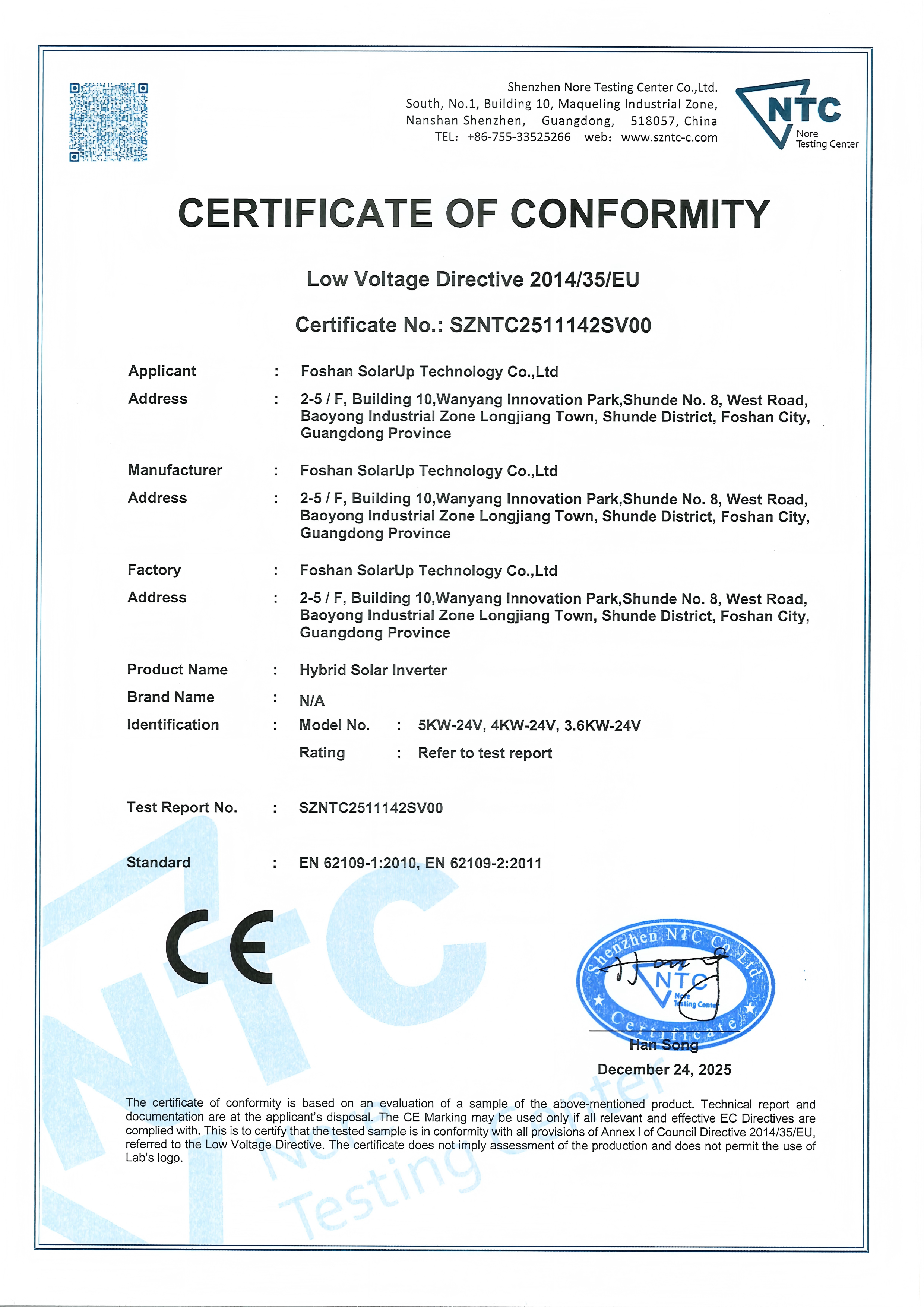
CE-LVD documentation in this product family cites EN 62109-1:2010 and EN 62109-2:2011. Model coverage on the certificate is the detail buyers must check.
Certification evidence is where hybrid inverter comparisons are most often decided on paperwork rather than performance. Three separate documents matter, and they do not cover the same products.
Low Voltage Directive file. Certificate numbers SZNTC2511142SV00 / SZNTC2511124SV00, issued by Shenzhen Nore Testing Center Co., Ltd. (NTC), cite standards EN 62109-1:2010 and EN 62109-2:2011 under Low Voltage Directive 2014/35/EU, with a scope covering the SYP hybrid inverter model list — the 1.5 kW, 2.5 kW, 4.0 kW, 6.5 kW and 12.0 kW entries, including the SYP12.0KW48V/P designation.
EMC file. Certificate CTC191J0808101EC, issued by Shenzhen Circle Testing Certification Co., Ltd. (C-CERT), covers solar hybrid inverter Model SYP-6.5KW-48V with additional models listed on the following page, and cites EN IEC 61000-6-3:2021, EN IEC 61000-6-1:2019, EN IEC 61000-3-2:2019/A1:2021 and EN 61000-3-3:2013/A2:2021 under EMC Directive 2014/30/EU, issued 11 September 2025.
RoHS file. Certificate CTC191J1202501RC, issued by Shenzhen Circle Testing Certification Co., Ltd., cites IEC 62321 series test methods and EN IEC 63000:2018 under RoHS Directive 2011/65/EU and (EU) 2015/863 — but its stated scope is the solar charge controller model list (VT8048, VT2024, VT4024, VT6048, MPQ1524 through MPQ6024, MPD2024 through MPD6024, MPJ1524 through MPJ6048, MRL2024 through MRL6048 and related entries). A buyer ordering inverters should therefore request a RoHS document that names the inverter model explicitly rather than assuming the controller declaration transfers.
Two further checks belong in the same file review. The international safety standard for PV power converters is IEC 62109, while UL 1741 is the primary safety standard for grid-connected inverters in North America, according to UL Solutions. Because the SYP range is specified as an off-grid inverter type, buyers targeting North American grid-tied interconnection should confirm the applicable local requirements separately rather than reading a CE file as global coverage. Separately, solar inverters are classified under HS Code 8504.40 as static converters, so customs treatment should be confirmed for the destination market.
Application fit and model selection checklist
Documented application industries for this product family are renewable energy and solar power systems, telecommunications base stations, marine and RV power systems, off-grid power supply, and street lighting. Working conditions described in the same specification set include continuous operation in variable weather, high-temperature environments up to 60 °C, and 24/7 uninterrupted power supply requirements. The battery range is specified as lithium and lead-acid, and BMS communication protocols should be confirmed against the compatibility list for the specific battery ordered.
| Model designation | Battery system class | Selection context |
|---|---|---|
| SYP1.5KW12V | 12 V | Smallest systems in the range; entry point for limited DC and lighting-oriented off-grid loads. |
| SYP2.5KW12V | 12 V | Small off-grid and mobile installations where a 12 V battery bank is already specified. |
| SYP4.0KW24V | 24 V | Mid-size off-grid loads, RV and marine power systems, small telecom or lighting circuits. |
| SYP6.5KW48V | 48 V | Residential off-grid storage; the configuration with the fully published parameter sheet (6.5 kW rated, 12 kVA surge, 9000 W PV input). |
| SYP12.0KW48V | 48 V | Larger residential and small commercial off-grid demand, including distribution-centre stocking. |
| SYP12.0KW48V/P | 48 V | Same certified model list as the other SYP entries; confirm the intended configuration with the supplier before ordering. |
Selection context is buyer guidance built on the documented application categories for this range — off-grid power systems, RV and marine, telecommunications and street lighting. Final sizing should follow the model datasheet.

Packing stage for a documented shipment of 2 × 40HQ containers, approximately 3,000–4,000 units, for a large-scale residential solar storage project in South Africa and for regional distribution stocking.
The strongest available field evidence for this architecture is a large-scale residential solar storage project in South Africa, supplied with 2 × 40HQ containers — approximately 3,000 to 4,000 units — for local use and global distribution. In that deployment the product replaced diesel generators and reduced fuel costs by 80%, operated stably at 45 °C without derating, and has run continuously for more than three years with a failure rate below 1%. The same case documentation notes lithium battery compatibility, fast delivery and professional technical support during installation, and records that the product has been used by large-scale solar EPC contractors and renewable energy system integrators.
Market trend analysis: what is moving around the charging decision
Third-party market research places the global solar hybrid inverter market at USD 10.7 billion in 2024, according to Grand View Research, while the residential sub-segment was valued at USD 4.55 billion in 2023 by Markets and Data. Product-mix data from Grand View Research also shows three-phase hybrid inverters holding a dominant revenue share of over 61.3% of the global market in 2024 — a reminder that single-phase off-grid platforms such as the SYP range address a specific slice of demand rather than the whole market.
Concentration at the top of the inverter market remains significant: Wood Mackenzie data shows Huawei and Sungrow combined for 55% of global PV inverter market share in 2024. That concentration matters to buyers evaluating independent suppliers, because component availability, certification paperwork and after-sales capacity become the differentiators rather than brand recognition alone. Forecasts for the category also diverge by methodology: Grand View Research projects an 8.1% CAGR for 2025–2030, while Precedence Research estimates 9.2% for 2025–2034, reflecting different forecast horizons and assumptions about off-grid demand. Buyers should treat any single growth figure as a scenario, not a fact.
Limitations and boundary conditions
A comparison that only lists advantages is not usable for procurement. The following boundaries apply to the built-in MPPT hybrid architecture described here.
- Indoor protection only. The inverter is rated IP21, which indicates protection against solid objects larger than 12.5 mm and vertically falling water drops. It is intended for indoor installation or a protected outdoor position such as under an eave, and should not be exposed to direct rain. Buyers who need an outdoor-rated enclosure should evaluate a different protection class; third-party commercial listings describe a GOTOSOLAR 8.2KVA 8200W 48V single-phase hybrid inverter with IP65 protection and parallel function capability as a separate offering in the wider portfolio.
- The 98% figure is a charging-stage figure. It describes MPPT conversion efficiency, not the efficiency of the whole system. Battery-mode inverter efficiency is separately published as 94% at 48 VDC, and system-level performance will be lower still once battery chemistry and load profile are included.
- Charge current is a ceiling, not a sum. PV and AC charging share a 120 A maximum, so a buyer planning around solar plus grid charging should model the combined limit rather than adding the two figures.
- PWM is not obsolete. Where the array voltage already matches the battery bank and the load is small, a PWM controller remains a valid low-cost choice with a published efficiency floor of 95% and a wider model spread in charging current from 10 A to 200 A.
- Battery communication needs verification. Lithium support is documented, but BMS communication protocols should be checked against the compatibility list for the exact battery model, because protocol mismatches are a common cause of commissioning delays.
- Altitude and temperature derating. Maximum operating altitude is 4000 m with derating above 1000 m, and the operating temperature window is −10 °C to 60 °C, with storage rated −15 °C to 60 °C. Installations outside these envelopes require separate engineering review.
Future outlook
Two forces are likely to shape this comparison over the next procurement cycles. The first is standardisation pressure: with IEC 62109 as the international benchmark for PV power converters and UL 1741 governing North American grid-connected inverters, buyers are increasingly requesting model-level certificate scopes rather than category-level claims — exactly the check that separates a valid CE file from a decorative one. The second is architectural convergence. As charge-controller efficiency floors move from the PWM habit of 95% toward the MPPT baseline of 98% and beyond, the separate-controller-plus-inverter configuration is likely to persist mainly in small, voltage-matched and retrofit installations, while integrated hybrid units absorb the residential, RV, telecom and street-lighting segments where one enclosure and one certification file simplify both installation and service.
For evaluation-stage buyers, the practical forecast is not a technology winner but a documentation shift: purchase orders will increasingly reference certificate numbers, aging-test durations and spare-part ratios alongside wattage. Suppliers prepared to publish those details — as this range does with its LVD and EMC files, its 4–8 hour aging test, and its 1%–2% spare-part practice — will be easier to qualify, and easier to defend internally when the project is audited.
FAQ
What is the difference in conversion efficiency between PWM and MPPT charging?
Published specification data for this product family states a conversion efficiency of at least 95% for PWM controllers and at least 98% for MPPT controllers. The difference comes from how each handles array voltage: PWM regulates the array toward battery voltage, while MPPT tracks the array's maximum power point across a wider voltage window.
Do I still need a separate charge controller if the hybrid inverter has a built-in MPPT charger?
No. A hybrid inverter with a built-in MPPT charger performs PV charging internally, with a documented MPPT operating range of 60–450 VDC, a 500 VDC maximum PV open-circuit voltage, 27 A maximum PV input current, 9000 W maximum PV input power, and a 120 A maximum charge current from PV and AC combined. A separate controller would be redundant unless a specific retrofit requirement demands it.
Which SYP model fits off-grid, RV, telecom or street-lighting loads?
The range is listed as SYP1.5KW12V, SYP2.5KW12V, SYP4.0KW24V, SYP6.5KW48V, SYP12.0KW48V and SYP12.0KW48V/P, with documented application categories of off-grid power supply, RV and marine power systems, telecommunications base stations, street lighting and residential solar storage. Smaller 12 V and 24 V models align with compact and mobile loads; 48 V models align with residential and larger off-grid demand. Final sizing should follow the datasheet for the chosen model.
Which CE documents should be checked before ordering a hybrid inverter?
Check three files. The Low Voltage Directive file (for this range, certificate numbers SZNTC2511142SV00 / SZNTC2511124SV00 citing EN 62109-1:2010 and EN 62109-2:2011) should name the ordered model. The EMC file (CTC191J0808101EC citing EN IEC 61000-6-3:2021 and EN IEC 61000-6-1:2019) should also list the model. A RoHS document should name the exact inverter model, because the RoHS declaration in this portfolio covers solar charge controller models rather than the inverter range.
What are the installation boundaries of an IP21 hybrid inverter with 120 A maximum charge current?
IP21 indicates protection against solid objects larger than 12.5 mm and vertically falling water drops, so the unit is intended for indoor or protected outdoor installation without direct rain exposure. The 120 A figure applies to the combined PV and AC charging path, not to each source separately. Operation is specified between −10 °C and 60 °C, and installation above 1000 m altitude requires derating, up to a maximum operating altitude of 4000 m.
Does the built-in MPPT hybrid inverter support both lithium and lead-acid batteries?
The published specification lists lithium and lead-acid as supported battery types, with a 48 VDC rated battery voltage, 54 V floating charge voltage and 61 V overcharge protection on the 48 V configuration. Because lithium support depends on BMS communication, the specific protocol should be confirmed against the compatibility list before the battery is ordered.
Reference material: the manufacturer's inverter catalogue is available for download at GOTOSOLAR inverter catalogue (PDF).