
Pan Assembly Busbar Procurement FAQ: Terminal Widths, Pole Distances and Current Ratings
Most pan assembly busbar procurement failures are not electrical. They are dimensional. A busbar can be correctly rated at 250A and still be unusable because the incoming terminal pads do not accept the lug, the branch pole distance does not match the MCCB, or the mounting plate does not align with the outgoing MCB footprint. This FAQ set answers the interface questions that panel builders and importers raise most often when specifying modular pan assemblies for low voltage distribution systems.
A pan assembly busbar is a pre-engineered copper distribution block that replaces point-to-point cabling inside a low voltage distribution board, feeding breakers through machined teeth instead of individual wire terminations. Because it is a mechanical interface as much as an electrical one, procurement decisions have to be validated on three axes at the same time: terminal geometry, device pole distance, and conductor thickness behind the stated current rating.

Modular pan assemblies shift the fit risk from the cable to the interface drawing, which is why the dimension questions below dominate procurement review.
Why Interface Dimensions Decide Fit Before Current Rating Does
A pan assembly is only installable when three measurements agree with the surrounding hardware. The incoming terminal interface has to accept the feed conductor or the upstream device output. The outgoing terminal interface has to match the branch breakers. The pole distance and device width have to align with the mounting plate and with the enclosure's usable width. Current rating then determines how much copper sits behind those interfaces, not whether the interfaces exist at all.
This ordering matters during evaluation because a datasheet can be entirely accurate and still leave a buyer without a decision. A rated current figure is a single number; an installation is a stack of tolerances. The practical approach used by experienced panel builders is to fix the mechanical envelope first, then confirm the electrical rating against the thermal and short-circuit requirements of the assembly.
FAQ Part 1 — Matching Incoming and Outgoing Terminal Widths
What do the terminal width figures on the BP6 actually describe?
The BP6 is a three-pole MCB chassis busbar with a rated current of 250A, a copper conductor with PC parts, an incoming terminal width of 21*22 mm and an outgoing terminal width of 6.5*12 mm.
The incoming figure describes the feed-side interface where the incoming conductor or upstream device connects. The outgoing figure describes the branch-side interface presented to the MCBs. The two are recorded in different formats — a pair of larger dimensions on the feed side and a smaller width-by-length pair on the branch side — which reflects the different hardware they receive: a feed lug or cable termination on one side, and repeated MCB teeth on the other. Buyers should treat these as interface footprints to be confirmed on a drawing rather than as interchangeable numbers, and should ask the supplier which axis corresponds to width and which to length on each side.
My incoming lug is narrower than the BP6 feed interface — is that a problem?
A narrower lug is generally less of a problem than a wider one, because the connection relies on the contact pad and fastener rather than on the lug filling the full pad area. The dimension that matters is whether the fastener spacing and pad orientation allow a correct, fully seated termination with the specified torque. What should trigger a stop is a lug that overhangs the pad, sits on an insulating edge, or forces the cable to bend against the enclosure wall. In those cases the terminal interface is wrong for the application regardless of the current rating.
Why is the BP5 outgoing terminal 15 mm while the BP6 outgoing terminal is 6.5*12 mm?
They serve different device families. The BP5 is an MCCB 2P pan assembly intended for branch DP MCCBs, with an incoming terminal width of 25 mm and an outgoing terminal width of 15 mm. The BP6 is an MCB-oriented chassis busbar, so its branch interface is dimensioned around MCB teeth rather than around a moulded case breaker terminal. A larger branch terminal on the BP5 is consistent with the larger branch device it feeds. This is the first rule of terminal matching: compare the terminal figures only between busbars intended for the same breaker family.
What happens if the outgoing MCB footprint does not match the standard BP6 plate?
The BP6 mounting plate can be customized according to the outgoing MCB. That is the documented customization path for footprint mismatch, and it is the correct route when a project specifies a breaker series whose terminal spacing differs from the standard plate. It is not the correct route when the mismatch is on the incoming side, because the feed interface is fixed by the busbar's conductor geometry rather than by the mounting plate.
FAQ Part 2 — Pole Distance and MCCB Width
What pole distance does the BP5 support for branch DP MCCBs?
The BP5 DP MCCB pan assembly can be used for branch DP MCCBs with a pole distance of 25 mm and a width of 50 mm.
That statement is a fit condition, not a preference. A 25 mm pole distance aligns the busbar teeth with the breaker terminals, and the 50 mm device width determines how closely branch breakers can be pitched along the assembly. The BP5 is available from 2W to 40W, so the number of ways is configurable, but the geometry of each individual way is fixed by those two numbers.
When do I need the BP3 instead of the BP5?
The BP3 is a three-pole MCCB pan assembly and is the appropriate series when the project uses 3P moulded case breakers or when the pole distance falls outside the DP specification. The BP3 series can be used with different brand MCCBs having pole distances of 25 mm, 30 mm, 35 mm or 45 mm, with incoming ratings of 250A, 400A, 630A and 800A and outgoing ratings of 125A, 250A and 400A, available from 2W to 14W. OEM is acceptable on this series and sizes can be customized to the customer's MCCB.
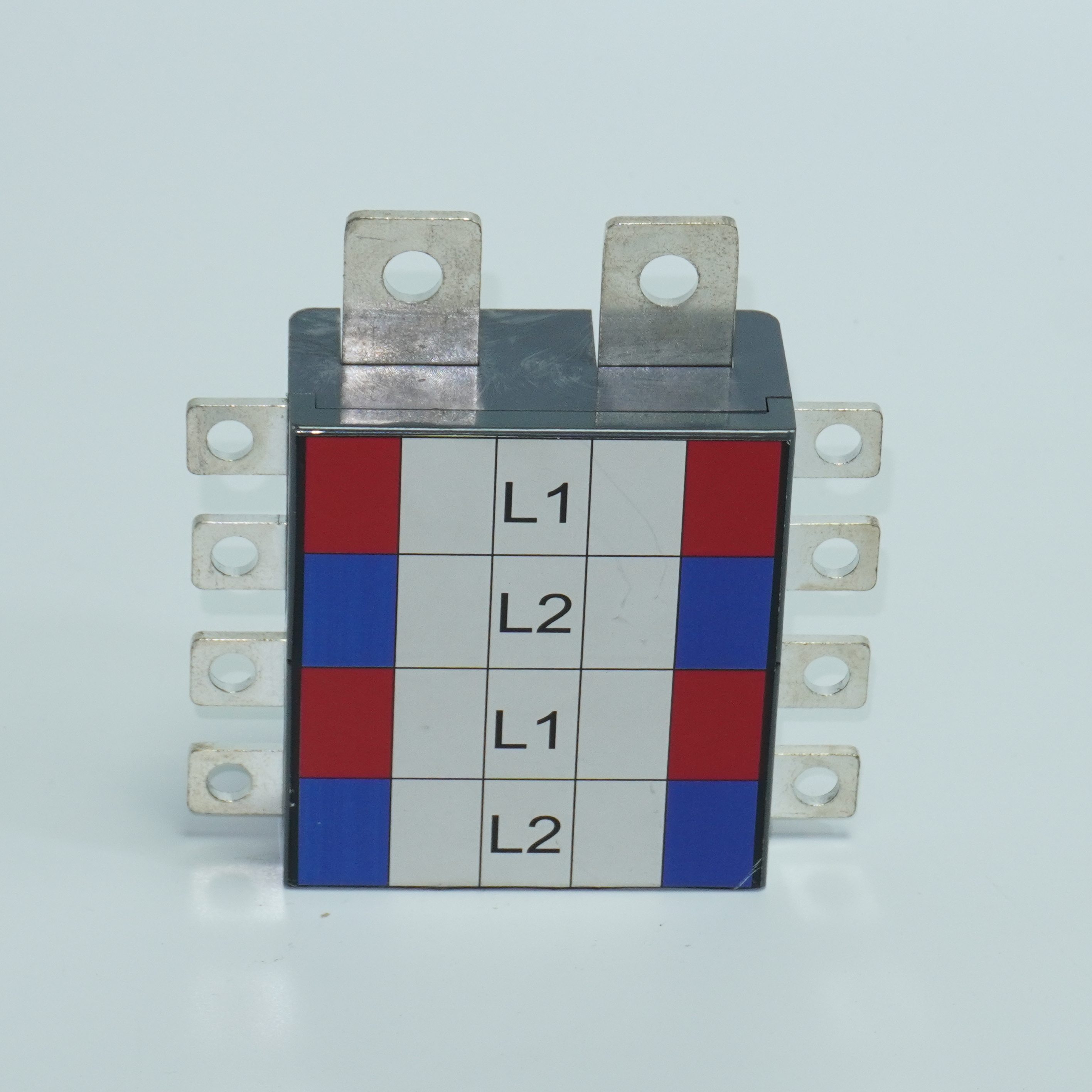
The BP5 is dimensioned around branch DP MCCBs with 25 mm pole distance and 50 mm device width, with 15 mm outgoing and 25 mm incoming terminal widths.
How does MCCB width affect whether the assembly fits the enclosure?
Device width sets the horizontal pitch of the branch positions, and pitch multiplied by ways sets the minimum internal width of the enclosure. A 50 mm branch device on a 40-way assembly occupies a very different enclosure from a 16-way assembly of the same device. This is why enclosure selection and busbar selection should be reviewed together: the DB02 distribution box with MCCB pan assembly busbar is offered from 2W to 16W with incomer options of 800A, 630A, 400A, 250A and 125A, while the DB01 with MCB pan assembly busbar is offered from 2W to 32W because MCB branch devices are narrower. Choosing ways first and enclosure second is a common cause of rework.
Does pole distance also affect whether neutral is switched?
No. Pole distance is a mechanical spacing between poles. Whether the neutral is disconnected together with the live conductor is a design characteristic of the busbar and breaker combination. The BP5 is designed for simultaneous live and neutral disconnection because it is a double-pole MCCB assembly for DP branch devices. Projects that require neutral isolation should therefore specify a DP assembly explicitly rather than inferring the behaviour from the pole distance alone.
FAQ Part 3 — Rated Current and Conductor Thickness
How is rated current tied to copper thickness in this range?
In the Barfuse pan assembly range, thickness is assigned per side and per rating rather than by a single universal rule. On the BP5, incoming ratings are 125A at T 4 mm, 250A at T 6 mm and 400A at T 10 mm, while outgoing ratings are 63A at T 2 mm and 125A at T 3 mm. On the BP4 single-pole MCB pan assembly, ratings are 125A at T 2 mm, 160A at T 2.5 mm and 250A at T 3 mm.
The pattern that emerges is consistent: current carrying capability rises with conductor thickness, and the thickness is specified separately for the feed side and the branch side because the two sides carry different currents.
Why does 125A appear at both 3 mm and 4 mm?
Because those two figures sit on different sides of the same busbar. In the BP5, 125A at T 3 mm is the outgoing rating for a single branch device, while 125A at T 4 mm is the incoming rating for the feed. The feed conductor carries the summed branch current plus design margin and therefore needs more copper for the same nominal current than an individual branch tooth. Reading a datasheet correctly means checking which side a rating belongs to before comparing it with another product.
Can a 250A-rated BP6 be used on a 400A feeder?
No. The BP6 is rated 250A. Projects needing a 400A, 630A or 800A incomer fall within the documented BP3 range, which lists incoming ratings of 250A, 400A, 630A and 800A. Substituting a lower-rated busbar because its terminal geometry happens to fit is one of the more serious procurement errors in this category, because the mechanical fit will hide the electrical shortfall until the assembly is loaded.
Is conductor thickness alone enough to confirm a rating?
No. Thickness is one variable among several, including conductor width, copper grade, plating, ambient temperature inside the enclosure, ventilation, mounting orientation and the short-circuit withstand required by the project. Component-level data supports the design, but assembly-level verification remains the panel builder's responsibility under the IEC 61439 series. Buyers should also note that the IEC 61439-6:2025 update published by the IEC addresses busbar trunking systems specifically, and should not be read across to modular pan assemblies as if it were the same product standard.
Interface Reference Table
| Model | Type | Rated current | Incoming interface | Outgoing interface | Ways | Notes |
|---|---|---|---|---|---|---|
| BP1 | MCB 3P pan assembly | 125A, 160A, 250A | Outline 2.0 x 20 mm | Connect size 2.0 x 5 mm | 6W–72W | DEKRA test certificate |
| BP2 | MCB 2P pan assembly | 125A, 250A; 220/240/120V | 3 x 15 mm | 2 x 5 mm | — | Branch: double pole MCB or RCBO |
| BP3 | MCCB 3P pan assembly | Incoming 250/400/630/800A; outgoing 125/250/400A | Per customer MCCB | Per customer MCCB | 2W–14W | Pole distances 25/30/35/45 mm; OEM acceptable |
| BP4 | MCB 1P pan assembly | 125A (T 2 mm), 160A (T 2.5 mm), 250A (T 3 mm) | 20 mm width | 5 x 11 mm (W x L) | 4W–72W | Single-pole MCB distribution |
| BP5 | MCCB 2P pan assembly | Incoming 125A (T 4 mm), 250A (T 6 mm), 400A (T 10 mm); outgoing 63A (T 2 mm), 125A (T 3 mm) | 25 mm width | 15 mm width | 2W–40W | Branch DP MCCB, pole distance 25 mm, width 50 mm |
| BP6 | MCB 3P chassis busbar | 250A | 21 x 22 mm | 6.5 x 12 mm | Per plate | Mounting plate customizable to outgoing MCB; compliant with IEC61439 and AS/NZS |
Dimensions as recorded in Barfuse product data. Some models record a single terminal width while others record a two-dimension interface — a mismatch worth confirming on drawing before ordering.
FAQ Part 4 — When Customization or OEM Is the Right Path
When does customization become justified rather than convenient?
Customization is justified when a documented fit condition fails. Three situations qualify: the branch device pole distance or width falls outside the standard options, the outgoing device footprint does not match the standard mounting plate, or the project standard fixes a breaker series whose terminal layout differs. In those cases a standard busbar cannot be installed correctly, and customization restores fit. Where only labelling, packing or colour differs, customization adds lead time without adding installation value.
What can actually be customized on a Barfuse pan assembly order?
Barfuse works in OEM and ODM modes and lists customization of colour, logo, material, new design, surface treatment, mould development and packing. At product level, the BP6 mounting plate can be customized according to the outgoing MCB, and the BP3 series can be sized to the customer's MCCB. Enclosure-level customization is also documented on the distribution box range, where painting is offered in textured RAL7032 or RAL7035 with customized specifications.
What are the minimum order quantity and typical lead time for an OEM build?
Barfuse lists a minimum order quantity of 1 piece, a lead time of 15–45 days and a monthly capacity of 8,000 pieces, with 100% testing and remote technical support after sale. The single-piece minimum is relevant during research and evaluation, because it allows a physical sample to be checked against the actual breaker before a project quantity is committed. The lead-time range, however, means customized geometry should be scheduled at the start of a project programme rather than at the point of installation.
What information should accompany an OEM request?
The minimum dataset for a reliable quotation is: breaker manufacturer and model, pole distance, device width, number of ways, incoming and outgoing current ratings, incoming and outgoing terminal dimensions, enclosure model and internal dimensions, target standard, and sample quantity. Requests that omit pole distance or terminal dimensions usually return with a question rather than a drawing, which adds a full round trip to the schedule. Buyers moving from research to evaluation should compile this dataset before first contact.
Where These Assemblies Are Applied
Modular pan assemblies are used in low voltage distribution systems for industrial application and commercial building electric management, typically in indoor installations operating continuously. The rated current band across the range runs from 125A, 160A and 250A through 400A, 630A and 800A, matched with circuit breakers as the primary equipment. Because the busbar replaces individual branch cabling, installation time and internal tidiness improve together, and the fixed tooth pitch reduces the risk of incorrect connection during assembly.
Enclosure choice follows the busbar choice. The DB01 distribution box with MCB pan assembly busbar, using copper pan assembly and steel sheet body, accepts an incomer of MCCB 250A, MCCB 125A or MCB 63A across 2W to 32W. The DB02 with MCCB pan assembly busbar covers incomers of 800A, 630A, 400A, 250A and 125A with MCCB branch devices across 2W to 16W. The DB13 waterproof low voltage distribution box is built to IP65 and IK10 with a 2.0 mm mounting plate, and is used where the installation environment requires a sealed enclosure rather than a standard sheet-steel box.
Market Context: Why Interface Discipline Is Becoming More Commercial
The busbar category is expanding, and that expansion is changing what buyers expect from suppliers. Precedence Research places the global busbar market at USD 19.83 billion in 2025, with copper busbars holding 62.8% of market share by material in the same year. The same source forecasts aluminum busbars growing at 6.9% CAGR over 2026–2035, driven largely by weight and cost considerations in large infrastructure. Laminated busbars used in high-density applications are forecast at 8.9% CAGR.
Two cautions should accompany those figures. First, market sizing in this category varies by methodology: Stratview Research reports a 2025 figure of USD 15.72 billion against IMARC's USD 20.3 billion, a gap generally attributed to whether locally fabricated busbars are counted alongside factory-assembled systems. Second, China's position in the supply chain is structural rather than incidental, with more than 30% of global copper processing capacity and refined copper output above 11 million metric tons annually. For buyers, the practical implication is that supplier availability is not the constraint; verification of interface data and standard compliance is.
Comparison with Traditional Wiring Approaches
Compared with point-to-point wiring using cable lugs and individual branch conductors, a modular pan assembly trades flexibility for repeatability. Installation is faster, the internal layout is fixed and therefore inspectable, and the tooth pitch removes a class of assembly errors. In projects with many identical branch ways, that repeatability is where most of the value sits.
The trade-off is real. A pan assembly fixes the geometry, so a board that mixes breaker brands, pole distances or device widths across branches becomes harder to serve with one standard busbar, and may require a customized plate or a mixed approach. At very low way counts, the material cost per way can exceed a simple wiring solution, and the assembly also depends on accurate upfront measurement — the same measurement discipline whose absence causes the fit failures described above. Pan assemblies reduce assembly risk; they do not remove the need for engineering review.
Future Outlook
Three directions are visible from the current data. Aluminum is gaining share on cost and weight grounds, which will push buyers to ask for material equivalence statements alongside copper specifications. Standards attention is intensifying, with the IEC 61439-6:2025 update for busbar trunking systems signalling continued movement in the wider assembly standards family. And customization demand is rising as panel builders standardize on specific breaker series rather than accepting generic footprints. Suppliers that document interface dimensions precisely will be easier to qualify than suppliers that publish only current ratings.
Before requesting a quotation, compile: breaker model and brand, pole distance, device width, number of ways, incoming and outgoing current ratings, terminal dimensions, enclosure model and internal size, target standard, and sample quantity.
The full Barfuse product range, including pan assembly busbars and distribution boxes, is documented in the catalogue: Barfuse Catalogue (PDF).