
Pan Assembly Busbar Selection: Certifications and Limits
Pan assembly busbars are selected under constraints, not preferences. Long before a buyer compares suppliers, the project has already fixed the electrical envelope, the breaker geometry, the enclosure, the certification evidence the inspecting authority will accept, and the material budget. Those boundaries decide which modular busbar is even eligible for the board.
This industry reference examines low-voltage pan assembly busbars as a constraint-driven component: what the term covers, which standards and certificates apply to which models, how the published BP series is specified, where the cost actually sits, and which limitations should be planned for before a purchase order is issued. It is written for importers, panel builders, distributors and procurement engineers working on industrial and commercial low-voltage distribution projects.
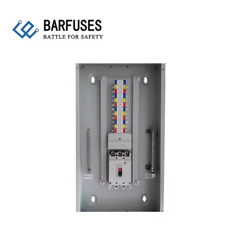
A pre-assembled pan assembly busbar replaces individually wired connections between the incoming device and the outgoing breaker row.
What Counts as a Pan Assembly Busbar
A pan assembly busbar is a pre-assembled conductor module that replaces individually wired connections between an incoming device and a row of outgoing devices inside a low-voltage distribution board. Rather than cutting, stripping and torquing a separate conductor for every outgoing breaker, the assembly provides a fixed conductor pattern with defined terminal geometry, so outgoing devices connect to prepared points with a repeatable pitch.
The category covers more than one product shape. In the published Barfuse range, the documented family includes MCB pan assembly busbars, MCCB pan assembly busbars, a comb busbar for distribution boards, and a chassis busbar model. Buyers also encounter the same component described as a feed pillar busbar, a plug-in busbar, a cabinet pan assembly busbar or a distribution box busbar. Those names generally describe the mounting position, the housing or the connection method rather than a different product standard — a distinction worth remembering when comparing quotations that appear to describe different products.
Barfuse Electric (Yueqing Barfuse Electric Co., Ltd.) is a Chinese low-voltage electrical manufacturer based in Yueqing, Zhejiang Province, producing fuse switch disconnectors, busbar systems and high- and low-voltage distribution wiring management products, including MCB pan assemblies and MCCB pan assemblies. The company reports a 10,000 m² factory, 45 employees, a seven-engineer R&D team, an annual output of 250,000 pieces and a 90% export ratio, with a documented export footprint in the Middle East, Russia, Latin America, Central Asia, the EU, Africa and Oceania.
Most assemblies must distribute three electrical paths: live, neutral and protective earth. In the published data, the DP MCCB assembly BP5 is described as providing simultaneous live and neutral disconnection. Earth (PE) distribution in these boards is normally handled by a separate earth terminal busbar inside the enclosure, which means the neutral terminal busbar and the earth terminal busbar are functional parts of the assembly design rather than accessories.
The Four Constraints That Decide Eligibility
Four constraint groups decide whether a pan assembly busbar can be used on a given project. Each one eliminates candidates independently, and each one is checked in a different document.
- Certification and standards evidence. Which standard applies, and what kind of document is being offered: a type test certificate for a named model range, or a quality management system certificate covering the manufacturing process. These are not interchangeable.
- Electrical envelope. Rated current, incoming and outgoing ratings, number of outgoing ways (W), and pole configuration — single-pole (SP), double-pole (DP) or three-pole (TP).
- Mechanical and geometry constraints. Pole distance of the breaker being used, terminal thickness and width, mounting plate pattern, and whether the module is used as a plug-in or bolt-on configuration.
- Commercial constraints. Conductor material content, customization scope, lead time, minimum order quantity, and customs classification of the shipped item.
The most common failure mode in specification is comparing catalogues by rated current only. A module rated at 250A can still be unusable if the outgoing breaker pitch does not match the device actually being installed, or if the certificate offered covers a different model in the series. Rated current is one constraint out of four.
Reading Certification Evidence Correctly
Two document types dominate busbar procurement, and buyers should read their scopes in full.
The first is a type test certificate. The BP1-125 and BP1-250 busbar panels are certified by DEKRA Certification B.V. under certificate numbers 3309992.100 and 3309992.101, issued on 5 September 2016. The certificate scope describes a low-voltage switchgear and controlgear assembly — busbar, models BP1-125 and BP1-250, brand BARFUSES, series BFSe, characterised as an open-type assembly without enclosure. The applicable standards named on the certificate are IEC 61439-2:2011 and EN 61439-2:2011.
The second is a quality management certificate. ISO 9001 certification number 62724Q1160R0S was issued by Jingxin Certification (Beijing) Co., Ltd. on 8 November 2024 and is valid to 7 November 2027, against the standard GB/T19001-2016 idt ISO 9001:2015. The certified scope covers the manufacturing and export of strip fuse disconnectors, load disconnectors, busbar systems (MCCB/MPCB busbars) and distribution boxes, plus the export of fuses and fuse bases. The company also reports testing accreditations from KEMA (DEKRA) in the Netherlands and VDE in Germany, plus CB certification and SAA certification in Australia.
Separately, the BP1 MCB pan assembly product data states compliance with CE and RoHS directives.
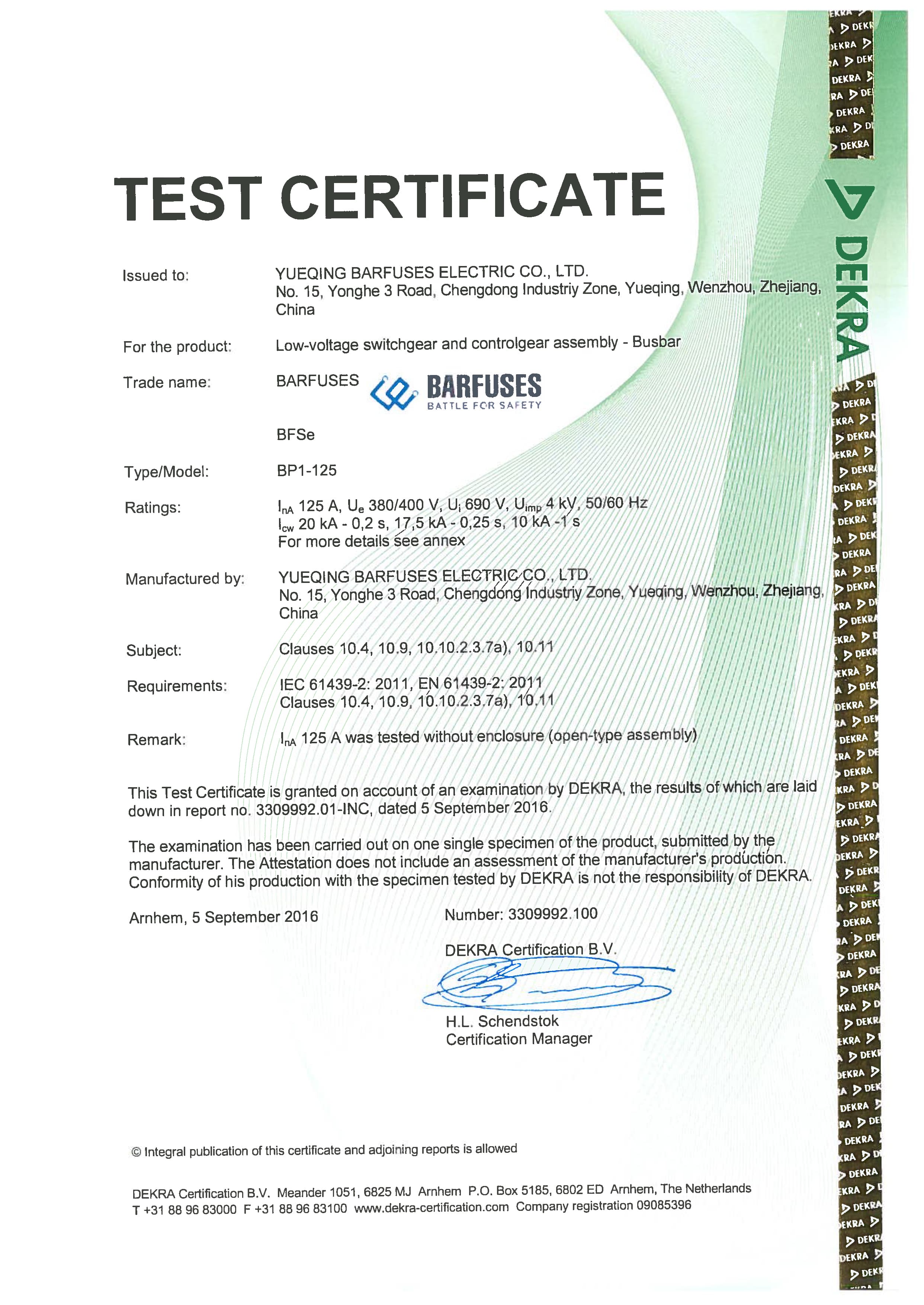
The published DEKRA type test certificate names the BP1-125 and BP1-250 panels; scope wording matters as much as the certificate number.
Two standard references that are frequently confused
IEC 61439-2 covers low-voltage switchgear and controlgear assemblies, and is the standard named on the BP1 type test certificate. IEC 61439-6:2025, listed as active and updated with an effective date of 1 December 2025, is titled “Low-voltage switchgear and controlgear assemblies — Part 6: Busbar trunking systems.” Busbar trunking systems are a different product category from an open-type busbar assembly mounted inside a distribution board. A specification that cites Part 6 for a pan assembly component is citing the wrong part of the series, and an offer that answers with a Part 6 document is not answering the question asked.
Specification Envelope of the Published BP Series
The table below summarises the published parameters of the Barfuse pan assembly range. In the product data, “W” denotes the number of outgoing ways, and terminal dimensions are given as thickness × width unless stated otherwise.
| Model | Configuration | Rated / incoming | Outgoing | Ways | Terminal and pitch detail |
|---|---|---|---|---|---|
| BP1 | MCB 3P pan assembly | 125A, 160A, 250A | — | 6W–72W | Connection size 2.0 × 5 mm; outline size 2.0 × 20 mm |
| BP2 | MCB 2P pan assembly; incomer MCCB or MCB, branch DP MCB or RCBO | 125A / 250A; 220/240/120V | DP MCB or RCBO | — | Incoming terminal 3 × 15 mm; outgoing terminal 2 × 5 mm |
| BP3 | MCCB 3P pan assembly; OEM accepted | 250A, 400A, 630A, 800A | 125A, 250A, 400A | 2W–14W | Suits MCCBs with pole distance 25 mm, 30 mm, 35 mm or 45 mm |
| BP4 | MCB 1P pan assembly busbar (comb busbar for distribution boards) | 125A (T2mm), 160A (T2.5mm), 250A (T3mm) | — | 4W–72W | Incoming terminal width 20 mm; outgoing terminal 5 × 11 mm |
| BP5 | MCCB 2P pan assembly busbar | 125A (T4mm), 250A (T6mm), 400A (T10mm) | 63A (T2mm), 125A (T3mm) | 2W–40W | Incoming terminal width 25 mm; outgoing terminal width 15 mm; branch DP MCCB pole distance 25 mm, width 50 mm |
| BP6 | MCB 3P chassis busbar | 250A | — | — | Incoming terminal 21 × 22 mm; outgoing terminal 6.5 × 12 mm; mounting plate customizable to the outgoing MCB |
“—” indicates that the figure is not stated in the published product data provided for this article. That matters for procurement: an empty cell is a question to put in writing to the supplier, not a gap to fill by assumption. BP1, BP2, BP4, BP5 and BP6 use copper conductors with PC (polycarbonate) insulating parts; the primary material of the BP1 MCB 3P pan assembly is stated as copper.
Material and Cost Constraints: Copper, Aluminum and Where Cost Sits
Conductor material is the single largest lever on busbar cost, and market data explains why copper remains the default in modular assemblies. Precedence Research estimates the global busbar market at USD 19.83 billion in 2025 and attributes 62.8% of that market to copper busbars by material. The same source projects a 6.9% CAGR for aluminium busbars between 2026 and 2035, attributing the faster growth to weight reduction and cost optimisation in large infrastructure rather than to a change in electrical requirements.
For pan assembly busbars specifically, the constraint is different from that of large trunking runs. A modular pan assembly sits inside a board, is dimensioned around the breaker footprint, and depends on a stable contact geometry. Weight savings rarely decide a 250A module; contact reliability, terminal thickness and available space usually do. This is why an aluminium busbar quotation for a pan assembly should be evaluated as a different engineering proposal — with its own terminal design, plating and torque specification — rather than as a direct swap for a copper part.
Other cost components in a pan assembly busbar procurement are less visible than the conductor:
- Insulating parts. The published BP range uses PC insulating parts alongside copper conductors, and the case material of the BP2 assembly is stated as PC.
- Way count and outgoing density. A 72-way assembly uses materially more conductor and terminal positions than a 6-way assembly of the same model.
- Customisation. Barfuse lists customization across colour, logo, material, new design, surface treatment, mold development and packing, with OEM and ODM production modes.
- Verification. The company states 100% testing in quality control and operates inspection equipment including a Rockwell hardness tester, an electric withstand voltage tester, a spring tester, a salt spray tester, a flame retardant tester and a switch tester.
No list price is published for these modules, and none should be inferred from this article. What can be compared objectively at the quotation stage is which of the four constraint groups each offer satisfies, and which evidence document is attached to it.
Compatibility Constraints: Pole Distance, Mounting Plates and Custom Assembly
Geometry is where most pan assembly busbar specifications succeed or fail, because the module must accept the breaker the project has already standardised on.
Pole distance is the first check. The BP3 series pan assembly is documented for use with different-brand MCCBs having pole distances of 25 mm, 30 mm, 35 mm or 45 mm, with incoming ratings of 250A, 400A, 630A and 800A and outgoing ratings of 125A, 250A and 400A. The BP5 DP assembly is documented for branch DP MCCBs with a pole distance of 25 mm and a width of 50 mm. Where a project uses a breaker brand outside these dimensions, the correct route is a customised mounting plate or a modified size rather than a forced fit.
Customisation is documented rather than implied. For the BP3, both the mounting plate and the size can be customised according to the customer’s MCCB, and OEM production is accepted. For the BP6 MCB 3P chassis busbar, the mounting plate can be customised according to the outgoing MCB configuration, and the product is stated to comply with IEC 61439 and AS/NZS standards.
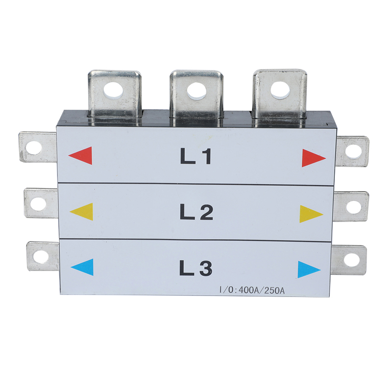
The BP3 MCCB 3P pan assembly is documented for breaker pole distances of 25 mm, 30 mm, 35 mm and 45 mm, and accepts customised mounting plates.
At the enclosure level, the pan assembly becomes part of a system. The DB01 distribution box combines a steel sheet body with a copper pan assembly busbar, an incoming MCCB at 250A or 125A or an MCB at 63A, MCB branch protection, and 2W to 32W configurations, finished in textured RAL7032 or RAL7035. The DB02 box pairs a steel sheet body with a copper pan assembly busbar, incoming MCCBs from 125A to 800A, branch MCCBs at 400A, 250A or 125A, and 2W to 16W configurations. These two models illustrate a practical rule: in sub-main distribution board designs, the constraint usually shifts from way count to incoming rating and device compatibility, and the busbar must be matched to that shift.
Pre-Assembled Busbars Compared with Conventional Field Wiring
The alternative to a pan assembly busbar is conventional field wiring: individual conductors cut, stripped and terminated on site between the incoming device and each outgoing breaker. The comparison is not about which method is universally better, but about which constraints each one handles well.
| Aspect | Pre-assembled pan assembly busbar | Conventional field wiring |
|---|---|---|
| Conductor routing | Fixed pattern established at the factory | Determined on site by the installer |
| Connection geometry | Pre-formed terminals with a defined pitch | Individual terminations, technique-dependent |
| Repeatability across boards | Same module repeated across units | Varies with installer and shift |
| Late design change | Requires a matching mounting plate or size revision | Often re-routable on site |
| Protection against ingress | Provided by the enclosure, not the busbar | Provided by the enclosure, not the wiring |
| Documentation | Model-level data and, where applicable, type test certificates | Documented per installation rather than as a tested component |
The clearest limitation sits in the first row of that table. A pre-assembled busbar is only as good as its match to the device it serves. If the breaker brand changes after the busbar is ordered, the module may no longer fit, and the remedy is a new mounting plate or a revised size — a lead-time event, not a site adjustment. Conventional wiring absorbs that change more easily, at the cost of repeatability.
Application Fit: Where the Range Is Documented to Work
The published application data for this product family is specific: industrial application and commercial building electric management, indoor working conditions, use in low-voltage distribution systems for power distribution and circuit protection, continuous duty, and matched equipment described as circuit breakers. The documented current range for the application is 125A, 160A, 250A, 400A, 630A and 800A, with a stated requirement for multiple current specifications, high-conductivity copper busbar, reliable electrical conductivity and ease of installation.
Typical configurations follow from the ratings:
- Distribution box busbar for MCB-based boards. BP4 (1P, 4W–72W), BP1 (3P, 6W–72W) and BP6 (3P chassis, 250A) suit boards where the outgoing devices are MCBs and the constraint is way count.
- DP modular pan assembly busbar. BP2 and BP5 serve two-pole and DP MCCB arrangements, including circuits requiring neutral disconnection; BP5 is documented for simultaneous live and neutral disconnection.
- TP pan assembly busbar for higher currents. BP3 covers three-phase MCCB arrangements from 250A to 800A incoming, with 2W to 14W outgoing positions.
- Complete distribution assemblies. DB01, DB02 and DB13 package the busbar inside a steel sheet enclosure. DB13 is documented with IP65 protection and IK10 impact resistance, with a 1.2–1.5 mm enclosure, a 1.2–1.5 mm door and a 2.0 mm mounting plate.
A Procurement Framework for Pan Assembly Busbar Constraints
The following sequence follows the order in which constraints eliminate options, so that a specification is not written around a product that cannot be certified or cannot fit.
- Fix the breaker first. Record brand, frame size, pole distance and width before selecting a busbar model. BP3 covers 25/30/35/45 mm pole distances; BP5 covers DP MCCBs at 25 mm pitch and 50 mm width.
- Define the electrical envelope. Incoming rating, outgoing rating, pole configuration (SP, DP or TP) and way count. Compare against the published envelope rather than against a single headline current.
- Confirm terminal geometry. Incoming and outgoing terminal thickness and width, plus overall busbar outline size, must match the assembly drawing — for example BP1 at 2.0 × 5 mm connection and 2.0 × 20 mm outline, BP6 at 21 × 22 mm incoming and 6.5 × 12 mm outgoing.
- State the certification requirement explicitly. Name the standard and the document type. Ask for the certificate scope and check that the model in your order appears in it.
- Decide the enclosure context. An open-type busbar assembly requires an enclosure to achieve an IP rating; a box such as DB13 carries its own IP65 and IK10 ratings, while the busbar inside it does not.
- Agree the commercial variables. MOQ, lead time, customisation scope and the customs description of the item, in that order.
Limits, Trade-offs and What the Data Does Not Cover
An honest constraint guide states boundaries, and several apply here.
The busbar does not provide ingress protection. The DEPKRA-certified BP1-125 and BP1-250 scope describes an open-type assembly without enclosure. Ingress protection belongs to the enclosure — IP65 for DB13 — and should never be attributed to the busbar alone in a specification or a customs document.
Certification is model-specific. The type test certificate published for this range names two models. Other models are covered by ISO 9001:2015 certification of the manufacturing system, which is a different assurance. A buyer who requires type-tested evidence for every model in a project must request it model by model.
Customisation has a time cost. The company publishes a lead time of 15–45 days and a monthly capacity of 8,000 pieces, with a minimum order quantity of one piece. A one-piece minimum removes the volume barrier but not the schedule risk: mounting plate and size customisation sit inside that lead-time band, so late geometry changes move the delivery date.
Aluminium is not documented for this range. Aluminium busbars are a real and growing market segment, but the published pan assembly data provided here describes copper conductors with PC insulating parts. Buyers seeking an aluminium pan assembly should treat it as a separate engineering and qualification exercise.
Customs classification is unresolved at category level. There is no single HS code for pan assembly busbars; trade data for these modules is generally aggregated under headings such as 8537 (boards, panels) or 8544 (insulated conductors). Importers should confirm the classification that applies to their specific configuration rather than relying on a generic category description.
Published data has gaps. Not every figure is stated for every model — BP2 way counts, for example, are not given in the product data, and only BP1 is documented with CE and RoHS compliance in the material reviewed. Gaps should be closed in writing before order confirmation.
Market Signals Relevant to Busbar Specification
Three market signals are worth tracking because they affect how pan assembly busbars are specified and sourced.
Growth with a methodological caveat. Precedence Research places the global busbar market at USD 19.83 billion in 2025, with a projection of around USD 29.96 billion by 2035. The same category is reported at USD 15.72 billion in 2025 by Stratview Research and USD 20.3 billion by IMARC. The gap is likely explained by whether locally fabricated busbars or factory-assembled trunking systems are included. Buyers citing a market figure in an internal business case should cite the source and its scope, not the number alone.
Material mix is shifting slowly, at the edges. Copper holds 62.8% of the market by material, while aluminium is forecast to grow at 6.9% CAGR from 2026 to 2035. In high-density applications, laminated busbars are reported by Congruence Market Insights at a CAGR of 8.9%. None of these trends changes the basic constraint on a pan assembly: it must match the breaker footprint and the terminal geometry of the board it serves.
Supply concentration. Congruence Market Insights notes that China accounts for over 30% of global copper processing capacity and produces more than 11 million metric tons of refined copper annually. For buyers, that concentration explains both the availability of copper busbar capacity and the importance of supplier-level quality documentation, since the material source is broadly the same while manufacturing discipline is not.
Future Outlook
The direction of travel in low-voltage distribution is toward pre-assembled, documented modules rather than field-fabricated connections. Three developments are likely to shape pan assembly busbar specification.
First, certification documentation will carry more weight than catalogue ratings. As inspection regimes tighten around IEC 61439 series compliance, the question shifts from “what is the rated current?” to “which certificate covers this exact model, issued by whom, against which edition of the standard?” The distinction between a type test certificate and a quality management certificate will become a routine procurement checkpoint rather than a specialist question.
Second, customisation will move from exception to expectation. Published capabilities already include OEM and ODM production modes, with customization across colour, logo, material, new design, surface treatment, mold development and packing. As distribution boards become more project-specific, mounting plate customisation — already documented for BP3 and BP6 — will increasingly be the deciding compatibility factor.
Third, material and weight considerations will continue to develop, particularly where aluminium busbars offer cost and weight advantages in large installations. Within modular pan assemblies, however, copper remains the documented conductor material for the range reviewed here, and any change would require its own terminal design, testing and documentation rather than a substitution.
FAQ
Which standard applies to a pan assembly busbar?
The BP1-125 and BP1-250 busbar panels are certified by DEKRA Certification B.V. to IEC 61439-2:2011 and EN 61439-2:2011, under certificate numbers 3309992.100 and 3309992.101, issued on 5 September 2016. The scope describes a low-voltage switchgear and controlgear assembly — busbar, brand BARFUSES, series BFSe, open-type assembly without enclosure. IEC 61439-6:2025 is titled “Busbar trunking systems” and addresses a different product category, so it is not the applicable part for a busbar module mounted inside a distribution board.
What materials are used in these pan assembly busbars?
The published range uses copper conductors with PC (polycarbonate) insulating parts. Copper is stated as the primary material of the BP1 MCB 3P pan assembly, and the BP2 assembly case material is stated as PC. At the enclosure level, DB01 and DB02 combine a steel sheet box body with a copper pan assembly busbar, while DB13 is manufactured from steel sheet with a 1.2–1.5 mm enclosure, a 1.2–1.5 mm door and a 2.0 mm mounting plate. Aluminium conductors are a separate market segment and are not documented in the pan assembly data reviewed here.
What current ratings are available across the range?
The documented ratings are: BP1 at 125A, 160A and 250A; BP2 at 125A and 250A with rated voltage of 220/240/120V; BP3 with incoming ratings of 250A, 400A, 630A or 800A and outgoing ratings of 125A, 250A or 400A; BP4 at 125A, 160A and 250A depending on busbar thickness (T2mm, T2.5mm, T3mm); BP5 with incoming ratings of 125A, 250A and 400A and outgoing ratings of 63A and 125A; and BP6 rated at 250A. The application data for the family references a working range of 125A to 800A in low-voltage distribution systems.
Can the pole pitch and mounting plate be customised?
Yes, within documented limits. The BP3 series pan assembly is stated for use with different-brand MCCBs having pole distances of 25 mm, 30 mm, 35 mm or 45 mm, and both its mounting plate and size can be customised according to the customer’s MCCB, with OEM production accepted. The BP6 MCB 3P chassis busbar’s mounting plate can be customised according to the outgoing MCB configuration. Barfuse also lists customization across colour, logo, material, new design, surface treatment, mold development and packing.
What commercial constraints apply to an order?
The published capability data states a minimum order quantity of one piece, a lead time of 15–45 days, a monthly capacity of 8,000 pieces and 100% testing in quality control, with remote technical support after sale. Customisation such as a new mounting plate or size falls within the quoted lead-time range, so geometry changes made late in a project affect the delivery schedule rather than being absorbed on site. Export coverage is documented for the Middle East, Russia, Latin America, Central Asia, the EU, Africa and Oceania, with an export ratio of 90%.
Reference document: the Barfuse low-voltage product catalogue, including busbar and distribution box ranges, is available as a PDF at https://cdn.socialarks.com/sbsp/24796/common/2026/0529/Barfuse%20Catalogue.pdf.
Есть вопросы или нужны дополнительные детали?
Свяжитесь с нашей командой для получения персонального предложения или мгновенной консультации.
Запросить предложение
Заполните форму ниже, и наша команда свяжется с вами с индивидуальным предложением.
Прямой чат WhatsApp
Предпочитаете общаться в реальном времени? Напишите нам в WhatsApp для мгновенной помощи и быстрых ответов.
- Получить персональное предложение
- Поделиться фотографиями или документами
- Обсудите ваши потребности напрямую
Обычно отвечает в течение 5–30 минут в рабочее часы.