
Power-Only vs 2+2 Power-Signal Combo Connectors: A Buyer Decision Framework
Power-Only vs 2+2 Power-Signal Combo Connectors: A Buyer Decision Framework
At the evaluation stage, OEM buyers often reduce the choice between a power-only high-current DC connector and a 2+2 power-signal combo to a single number: amperage. That is a costly simplification. The connector architecture determines how many harnesses run through the enclosure, how the BMS signal path is terminated, how the interface is sealed, and what the incoming inspection plan must prove.
AOYG DC Power Connector is a manufacturer of high-current DC connection systems for lithium-ion smart devices and new-energy applications. Its range includes single-purpose power connectors and the DXT30U(2+2)-F(B) female combo, which carries two power pins and two signal pins. The company operates a 6,000 m² facility with 100 employees and 25 engineers, and its products are exported to Europe, America, and Southeast Asia. Those facts matter because the decision framework below is not a generic connector tutorial; it is a way to compare two architectures against a real program.
The core answer is straightforward. Choose a power-only connector when the main power link is above the combo's current envelope or when no low-current signal needs to cross the connector. Choose a 2+2 combo when the load fits within 20 A per power pin and 35 A peak, and when two low-current signals can be integrated without compromising sealing, pinout control, or serviceability. Neither choice is automatically superior.
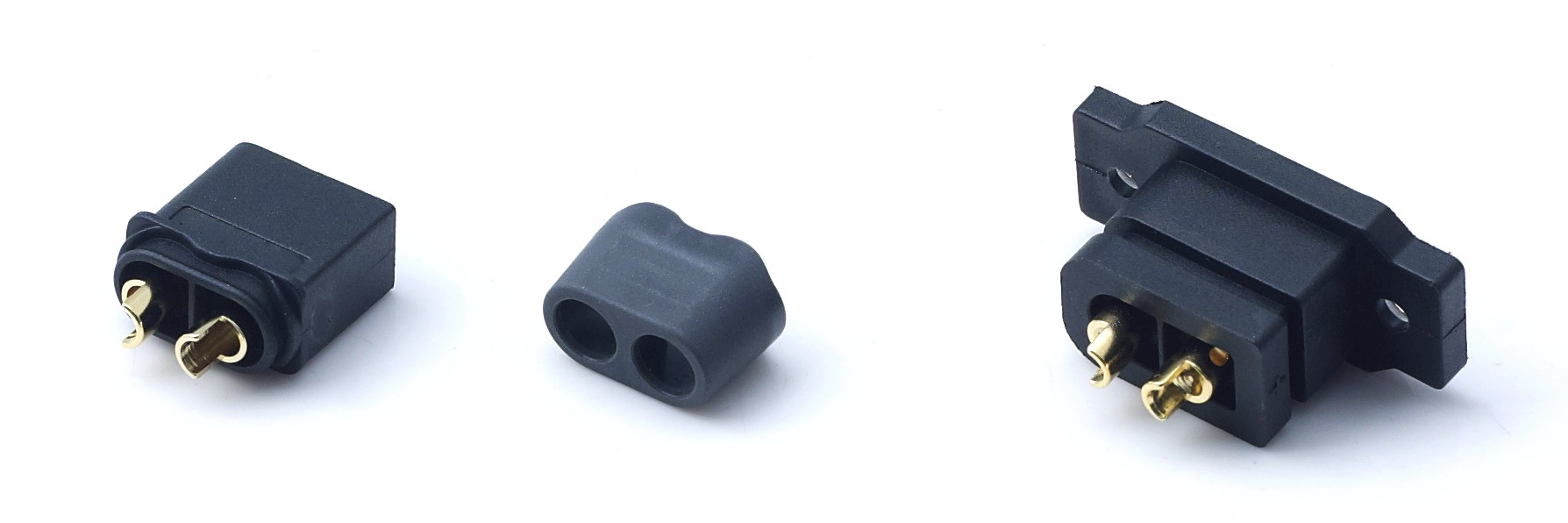
Two architectures, one decision
A power-only high-current DC connector has two power contacts and no signal contacts. In the evaluated class, power-only options are commonly specified at 45 A or 90 A continuous, with DC 500 V, -20°C to +120°C operation, IP40 standard with IP67 optional, UL94 V-0 flame-retardant housing, anti-spark pre-charge mating, and 1000+ mating cycles. Compliance includes RoHS 2.0, REACH SVHC, and IATF16949 quality control.
The DXT30U(2+2)-F(B) is a female connector with two power pins and two signal pins. It is rated 20 A power per pin, 1 A signal, and 35 A peak. The same environmental and compliance envelope applies: DC 500 V, -20°C to +120°C, IP40 standard with IP67 optional, UL94 V-0, anti-spark pre-charge mating, 1000+ mating cycles, RoHS 2.0, REACH SVHC, and IATF16949 quality control.
Read those ratings literally. The combo is not a 90 A power connector with two extra pins. Its power pins are rated at 20 A each; the 35 A figure is a peak, not a continuous rating. A 45 A or 90 A power-only connector occupies a different current class. That is the first boundary in the decision framework, and it should be settled before harness design begins.
| Decision parameter | Power-only high-current connector | DXT30U(2+2)-F(B) combo |
|---|---|---|
| Contact layout | 2 power contacts | 2 power contacts plus 2 signal contacts |
| Continuous current | 45 A or 90 A, depending on model; 90 A is the high-current benchmark in this class | 20 A power per pin |
| Signal current | None at the power connector | 1 A signal per signal pin |
| Peak current | Model-dependent | 35 A peak |
| Voltage | DC 500 V | DC 500 V |
| Operating temperature | -20°C to +120°C | -20°C to +120°C |
| Sealing | IP40 standard; IP67 optional | IP40 standard; IP67 optional |
| Housing flammability | UL94 V-0 | UL94 V-0 |
| Mating cycles | 1000+ | 1000+ |
| Pre-charge feature | Anti-spark pre-charge mating | Anti-spark pre-charge mating |
| Compliance | RoHS 2.0, REACH SVHC, IATF16949 | RoHS 2.0, REACH SVHC, IATF16949 |
| Best-fit role | Main battery or DC power link where no signal crosses the connector | Battery or module interface that needs two low-current signals and fits the 20 A per-pin envelope |
| Main limit | No integrated signal path; a separate signal connector may be required | Lower current per power pin; not a 90 A substitute |
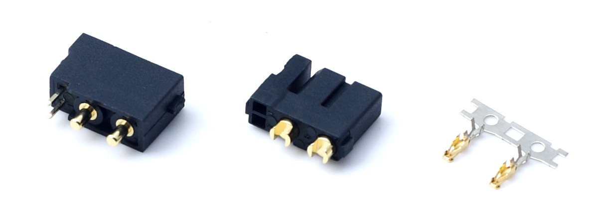
Where the decision shifts: BMS and signal routing
The connector decision should start at the BMS interface, not at the connector catalogue. A power-only architecture is efficient when the BMS is packaged near the battery and the signal path never crosses the main power interface. It keeps the power connector dedicated to current transfer and avoids trading signal routing for mechanical integration.
When the pack or module needs low-current signals at the interface, the 2+2 combo can carry two such lines in the same shell. The signal pins are rated 1 A, so they fit low-current enable, identification, or sensor lines. They are not a power rail, and they do not replace a dedicated communication connector if the design needs more than two signal lines or a different signal architecture.
Buyers should count signal lines before counting connector pins. If the BMS needs two signals, the combo is a candidate. If it needs four, the combo is not a complete answer. If it needs none, the combo adds a feature the program may not use. That is a functional test, not a preference test.
Harness count and assembly time
Harness count is where the two architectures diverge commercially. A power-only design usually needs a separate signal connector when a signal exists. That adds a housing, terminal set, seal, strain relief, labeling, continuity check, and mating inspection. A 2+2 combo removes one connector pair, but it adds pinout definition, keying discipline, and signal verification within the same housing.
The relevant metric is total landed assembly effort, not connector unit price. Two inexpensive connectors can cost more to assemble and inspect than one integrated connector. One integrated connector can be more expensive to rework if a signal pin is miswired. The evaluation should compare connector count, termination count, test steps, and field-service procedure.
Assembly time savings should not be assumed. Ask for sample assemblies and run a pilot build. The pilot should confirm the termination process, mating force, pin retention, and the inspection method for the two signal lines. A connector that reduces part count but increases debug time is not automatically the lower-cost choice.
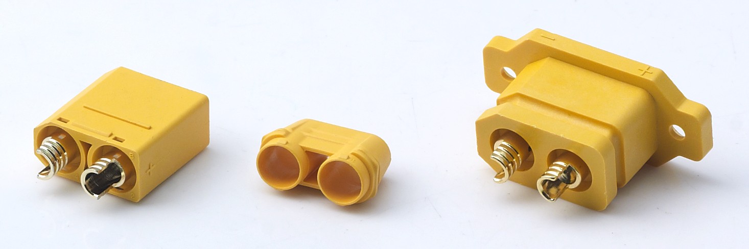
Sealed or non-sealed enclosure strategy
IP40 is the standard rating in the compared family; IP67 is optional. The enclosure strategy should decide the requirement. If the connector is inside a sealed battery box or control enclosure, IP40 may be sufficient. If the interface is exposed to rain, washdown, or temporary immersion, specify IP67 and verify the option.
Sealing is an interface property. The buyer should confirm that sealing performance is defined for the mated condition used in the design, and that the optional IP67 version does not conflict with the enclosure gasket, cable jacket, or service loop. For the combo, the signal cavity adds another path that must be sealed and inspected.
Adding IP67 is not a marketing upgrade. It changes the interface stack and should be tied to an explicit test and acceptance requirement. A sealed connector inside an unsealed enclosure does not solve the enclosure problem. An unsealed connector inside a sealed enclosure may be the rational choice if the enclosure strategy is verified.
Purchasing terms and acceptance criteria
Purchasing terms should be written around evidence, not adjectives. AOYG reports 100% test quality control, a MOQ of 2 units, a lead time of 30-45 days, monthly capacity of 8,000 units, and remote after-sales support. Its product line has been adopted by manufacturers of drones, robots, e-mobility, energy storage, and power tools.
The acceptance file for a power-only or combo connector should include the IATF16949:2016 certificate and scope, ISO9001:2015, UL94 V-0 test report, RoHS 2.0 test report to IEC 62321 series, REACH SVHC test report, electrical performance test report to IEC 60512 and GB/T 5095, salt spray test report to GB/T 10125 and ASTM B117, and CE-LVD declaration to EN 61984 where applicable.
Then attach the drawing, pin assignment, sealing option, marking, packaging, and sampling plan. The purchase order should state the exact model, the power and signal pin assignment, and the acceptance test method. A certificate without the model and scope is not an acceptance criterion.
| Evidence area | Document or control | What the buyer should verify |
|---|---|---|
| Quality system | IATF16949:2016; ISO9001:2015 | Certificate scope covers the supplied product line |
| Flammability | UL94 V-0 test report | Report applies to the housing material and exact model |
| RoHS 2.0 | IEC 62321 series test report | Report covers the exact model and date |
| REACH SVHC | ECHA candidate list test report | Report identifies the SVHC screening basis |
| Electrical performance | IEC 60512; GB/T 5095 | Test items and sample identity match the purchase order |
| Corrosion | GB/T 10125; ASTM B117 | Salt spray test is relevant to the exposed interface |
| Safety declaration | CE-LVD; EN 61984 | Declaration applies to the product and market |
| Production control | 100% test | Test method, pass criteria, and traceability are defined |
A buyer scorecard for objective comparison
Use a weighted scorecard to keep the evaluation consistent. The weights below are an example for an OEM program; adjust them to the duty cycle, enclosure strategy, and service model. Score each candidate from 1 to 5 and multiply by the weight. A candidate that wins on unit price but loses on sealing evidence or signal routing can still rank lower.
| Evaluation criterion | Example weight | What to score | Evidence to request |
|---|---|---|---|
| Current margin | 25% | Continuous load versus 20 A per power pin, 35 A peak, or 45 A / 90 A power-only rating | Rating basis, temperature assumptions, and test report |
| Signal need | 20% | Number of low-current signals and whether 1 A is acceptable | Pin assignment and signal definition |
| Harness and assembly | 15% | Connector count, termination count, test steps, and serviceability | Drawing, sample build, and inspection plan |
| Sealing strategy | 15% | IP40 versus IP67, enclosure exposure, and mated-condition definition | Sealing option and test evidence |
| Compliance file | 10% | IATF16949, UL94 V-0, RoHS 2.0, REACH SVHC, and electrical test coverage | Certificates, reports, and scope statements |
| Durability | 5% | 1000+ mating cycles and anti-spark pre-charge mating | Mating cycle and pre-charge evidence |
| Supplier support | 10% | Matching, debugging, samples, and after-sales response | Technical support plan and remote support terms |
The scorecard is not a substitute for sample validation. It is a way to make the sample test plan explicit. If a supplier cannot provide the evidence behind a score, the score should be treated as unverified.
Application fit: where each architecture belongs
Power-only fits high-current battery links in drones and RC models, e-mobility, energy storage, power tools, garden tools, 5G backup, and other links where the connector's job is current transfer. The 45 A / 90 A options provide headroom that the combo does not. If the BMS signal is handled elsewhere, or no signal exists at the connector, the power-only design is the simpler starting point.
The 2+2 combo fits smart robot battery interfaces, battery exchange cabinets, smart home power modules, compact energy-storage modules, and other designs where two low-current signals must cross the same interface and the load is within 20 A per power pin. It is a system-integration part, not a universal replacement. The buyer should verify the exact current, signal count, and sealing option before design freeze.
AOYG's line has been adopted by manufacturers of drones, robots, e-mobility, energy storage, and power tools. The correct reading is not that one architecture fits all those applications. It is that the supplier has reference exposure across them, which is useful when asking for application-specific matching and sample support.
Market trend: more power, more signals, tighter interfaces
Fact.MR valued the global high power connectors market at about USD 5.47 billion in 2025. Dataintelo reported that DC connectors represented 58.7% of the energy storage connector market in 2025. 5G base stations draw 11.5-14 kW typical, peaking at 19 kW. These data points describe demand pressure: more power, more compact interfaces, and more monitoring.
The trend does not make the 2+2 combo the default. It makes the evaluation more explicit. Higher power density raises the cost of a wrong current rating; more signal content raises the value of a controlled signal path. The buyer should separate the two trends and score them separately.
Limitations: where the combo is the wrong choice
- The load exceeds 20 A per power pin or treats the 35 A peak as a continuous condition.
- The design needs more than two low-current signal lines.
- The interface is exposed and IP67 is required, but the sealing option is not validated for the enclosure.
- The program has no signal at the connector; the combo adds pinout and inspection complexity without a functional benefit.
- The assembly process cannot control signal pin assignment or verify continuity.
Power-only has its own limits. It cannot carry integrated signal, and a separate signal connector may add harness count. It is not a lower-cost answer if the separate connector and assembly steps are counted. The decision should be made on total system fit, not on a single headline rating.
Questions to ask the supplier before awarding
These questions turn the framework into a supplier comparison. They are especially useful when the candidate list includes both power-only and 2+2 combo options.
- What is the basis of the 20 A power and 35 A peak ratings, including continuous condition, temperature, and termination assumptions?
- Can you provide the drawing, 3D model, pin assignment, and mating and unmating definition for the exact model?
- Is IP67 an option on the exact model, and what sealing evidence is available for the mated condition used in the design?
- Which test reports are available for the exact model: IEC 60512, GB/T 5095, UL94 V-0, RoHS 2.0, REACH SVHC, and salt spray?
- What is the IATF16949 certificate scope, and does it cover this product line?
- How is anti-spark pre-charge mating implemented, and what system condition does it assume?
- What evidence supports the 1000+ mating cycle claim?
- Can you support customization of pin position, wiring, and logo? What are the MOQ and lead time?
- What technical support is available for product matching and debugging during sample and pilot builds?
- What are the acceptance criteria, packaging, traceability, and after-sales response terms?
FAQ
Is the DXT30U(2+2)-F(B) a direct replacement for a 90 A power-only connector?
No. The DXT30U(2+2)-F(B) is rated at 20 A power per pin, 1 A signal, and 35 A peak. A 90 A power-only connector belongs to a different continuous current class. The combo should be selected only when the load fits its 20 A per-pin envelope and two low-current signals are needed.
What are the two signal pins intended to carry?
The signal pins are rated at 1 A. They are intended for low-current signal paths, not for main power or high-current return. If the design needs more than two signal lines, or a signal path outside the 1 A rating, the combo is not a complete interface.
Do I need the IP67 option or is IP40 sufficient?
IP40 is the standard rating in the compared family; IP67 is optional. The choice depends on the enclosure strategy. A connector inside a sealed enclosure may not need IP67. An exposed interface may need it. The buyer should confirm the sealing requirement for the mated condition used in the design.
Which compliance documents should be in the acceptance file?
The file should include IATF16949:2016 and ISO9001:2015 certificates with scope, UL94 V-0 test report, RoHS 2.0 test report to IEC 62321 series, REACH SVHC test report, electrical performance test report to IEC 60512 and GB/T 5095, salt spray test report to GB/T 10125 and ASTM B117, and CE-LVD declaration to EN 61984 where applicable.
How many mating cycles are specified?
The compared product family is specified for 1000+ mating cycles. The buyer should ask for the mating cycle evidence for the exact model and confirm that the service model does not exceed the tested condition.
Can the connector be customized for an OEM program?
AOYG supports OEM and ODM customization, including size, current specification, pin position, wiring structure, and logo printing. The reported MOQ is 2 units, lead time is 30-45 days, and production includes 100% test quality control.
This analysis is based on the supplied product and compliance information for AOYG DC Power Connector and on the cited third-party market data. Buyers should validate final application fit through drawings, samples, and program-specific testing.
Есть вопросы или нужны дополнительные детали?
Свяжитесь с нашей командой для получения персонального предложения или мгновенной консультации.
Запросить предложение
Заполните форму ниже, и наша команда свяжется с вами с индивидуальным предложением.
Прямой чат WhatsApp
Предпочитаете общаться в реальном времени? Напишите нам в WhatsApp для мгновенной помощи и быстрых ответов.
- Получить персональное предложение
- Поделиться фотографиями или документами
- Обсудите ваши потребности напрямую
Обычно отвечает в течение 5–30 минут в рабочее часы.