
Qualifying RobotScan Series: ISO 10360 / VDI/VDE 2634 Checklist
Qualifying RobotScan Series: ISO 10360 / VDI/VDE 2634 Certificate Checklist
Automated optical inspection has moved past the pilot stage in smart manufacturing. Tolerances are tightening — EV battery-pack tolerances as tight as 0.025 mm are pushing automakers to replace manual gauges with automated optical scanners — and the purchasing conversation has changed shape. The question is no longer only "how accurate is this scanner?" It is "which accuracy can you document, against which standard, tested in which laboratory, for which configuration?"
That question is harder to answer for an automated cell than for a standalone instrument. A certificate describes a scanner. A buyer is qualifying a system — scanner, robot, turntable, fixture and inspection software together. This article sets out a practical certificate checklist for teams qualifying the RobotScan Series for automated inline parts inspection, using SHINING 3D's published metrology documentation as the working example.
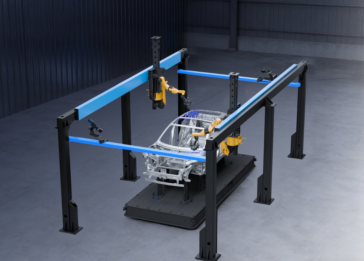
RobotScan Series configured on a servo gantry: the accuracy chain in an automated cell runs through the scanner, the robot, the turntable and the fixture, not through the scanner alone.
Why accuracy claims stall during qualification
Two different documents are routinely confused in early supplier discussions. The first is a specification: a headline accuracy figure such as 0.02 mm, usually stated for a defined measuring volume. The second is evidence: an acceptance test report issued against a named standard, plus a calibration certificate traceable to metrology standards. The specification is what a supplier advertises. The evidence is what a quality department can file, review and defend.
In an automated cell the evidence chain is longer than in a handheld scenario. Measured accuracy depends on the scanner head, the robot arm that positions it, the turntable that indexes the part, the fixture that locates it, and the inspection software that converts point clouds into a pass or fail verdict. Every element can be documented, and every element can be left undocumented. Qualification projects tend to stall exactly there: the buyer asks for a certificate, receives a model-name claim, and has no basis for accepting or rejecting it.
The practical response is not to treat certificate claims as unreliable, but to make them specific. A checklist converts a general assurance into a defined set of documents that can be reviewed before purchase, filed with the asset, and re-verified at the next internal or customer audit.
What the RobotScan Series is, and what it publishes
SHINING 3D (Shining 3D Tech Co., Ltd.) is a 3D vision technology company established in 2004 and headquartered in Hangzhou, China, with subsidiaries in Stuttgart, Barcelona, California, Florida and Tokyo, and a headquarters facility of nearly 140,000 m². The company employs 1,367 people, 533 of them in R&D, operates an export ratio of roughly 70% across EU, USA and APAC markets, and reported operating revenue above USD 220 million in 2025. Its portfolio spans metrology, professional, entry-level and dental 3D scanning, with over 330 authorized patents and more than 230 software copyrights.
RobotScan Series is the company's automation family rather than a single instrument. It is described as an automation solution combining a high-accuracy 3D scanner with an industrial robot and a collaborative robot, and it is offered in three named configurations:
- RobotScan Q12 — fringe projection measurement aimed at small parts with complex surfaces, geometries or sharp edges, including fine-detail components such as airfoils, brackets, connectors, gears, housings and electronic components. It is positioned for automated optical measurement in mass-production inspection where repeatability and throughput both matter.
- RobotScan UE Pro2 — handheld blue laser scanning with strong adaptability to black, shiny and reflective surfaces, aimed at small and medium sheet metal parts, casting housings, machining parts and mold components, with wireless and wired connectivity for flexible on-site integration.
- RobotScan Combo+ — a hybrid light source configuration for efficient batch inspection of small-to-medium castings and machined parts and for mixed-size components such as covers, trim pieces, assemblies and medium castings, positioned as a cost-effective option for manufacturers with diverse inspection needs.
Published system parameters define the working envelope: measurable object size up to 500 mm, turntable load capacity up to 20 kg, a robot working radius of 800 mm and a system weight of 70 kg. The series is also customizable — the robotic arm brand, the SHINING 3D scanner head, the turntable, the fixtures, and the control and inspection software can all be specified to the application.
That flexibility is commercially attractive, and it is precisely why a certificate must be read carefully. A configuration-specific document is what a quality system can absorb; a brand-level claim is not.
What ISO 10360 and VDI/VDE 2634 actually cover
Both are acceptance frameworks rather than marketing labels, but they cover different ground and are often quoted interchangeably. Three references matter for a qualification file.
VDI/VDE 2634 Part 3 is the primary standard for evaluating the accuracy of optical 3D measuring systems based on area scanning. Because it targets area-scanning optical systems, it is the framework most commonly cited for structured-light and laser scanners deployed on the shop floor.
ISO 10360 is a multi-part international standard for the acceptance and reverification of coordinate measuring systems. Its individual parts address different machine types: ISO 10360-12, for example, establishes international requirements for the acceptance and reverification of articulated arm coordinate measuring machines. A supplier statement such as "ISO 10360 certified" is therefore incomplete until the buyer knows which part number and which measuring volume were tested.
ISO/IEC 17025 is the accreditation that sits underneath both. It is widely treated as a critical verification requirement for laboratories publishing 3D scanner accuracy data, because it establishes the technical competence behind the numbers rather than the numbers alone.
Applied to the scanner platforms used in RobotScan configurations, SHINING 3D's published position is that inspection reports and calibration certificates are traceable to international standards such as VDI/VDE 2634 and ISO 10360, subject to the actual certificates issued, and that all calibration and verification procedures are performed in the company's accredited Accuracy Lab, which operates in accordance with ISO/IEC 17025 requirements.
| Scanner platform | Documented acceptance test | Test environment |
|---|---|---|
| OptimScan Q12/Q9 (fixed blue LED structured light) | VDI/VDE 2634 and ISO 10360-13 | ISO/IEC 17025 accredited lab |
| OptimScan Q12/Q9 HD (high-precision fixed) | VDI/VDE 2634 Part 2 and ISO 10360 | ISO/IEC 17025 accredited lab |
| FreeScan Combo Series (handheld hybrid light source) | VDI/VDE 2634 Part 3 and ISO 10360 | ISO/IEC 17025 accredited laboratory |
| FreeScan Combo+ Wireless / Combo Wireless | ISO 10360 | ISO/IEC 17025 accredited Accuracy Lab |
| FreeScan UE Nova (large-FOV handheld blue laser) | VDI/VDE 2634 Part 3 and ISO 10360 | Accredited acceptance testing |
| FreeScan Trak Nova Series (dynamic tracking) | VDI/VDE 2634 Part 3 and ISO 10360 | ISO/IEC 17025 accredited accuracy lab |
| FreeScan Omni / FreeScan Omni Lite (standalone) | VDI/VDE 2634 Part 3 and ISO 10360 | ISO/IEC 17025 accredited lab; on-device inspection PTB-certified |
Source: SHINING 3D published product documentation and citable product statements.
Platform-level accuracy figures are published per design rather than per brand: 0.02 mm for the handheld hybrid light source platform, 0.072 mm for the large-field-of-view handheld platform, and 0.005 mm (small range) to 0.015 mm (large range) for the fixed blue light platform. Buyers comparing a RobotScan cell against a handheld workflow should note that these figures describe different optical architectures serving different part families, not a ranked list.
Read together, the table shows a rule that applies to every metrology supplier: acceptance-test coverage is published per platform and per standard part, not per company. The same catalogue can contain products with different documentation depth, and the checklist below is designed to surface that difference before a purchase order is issued.
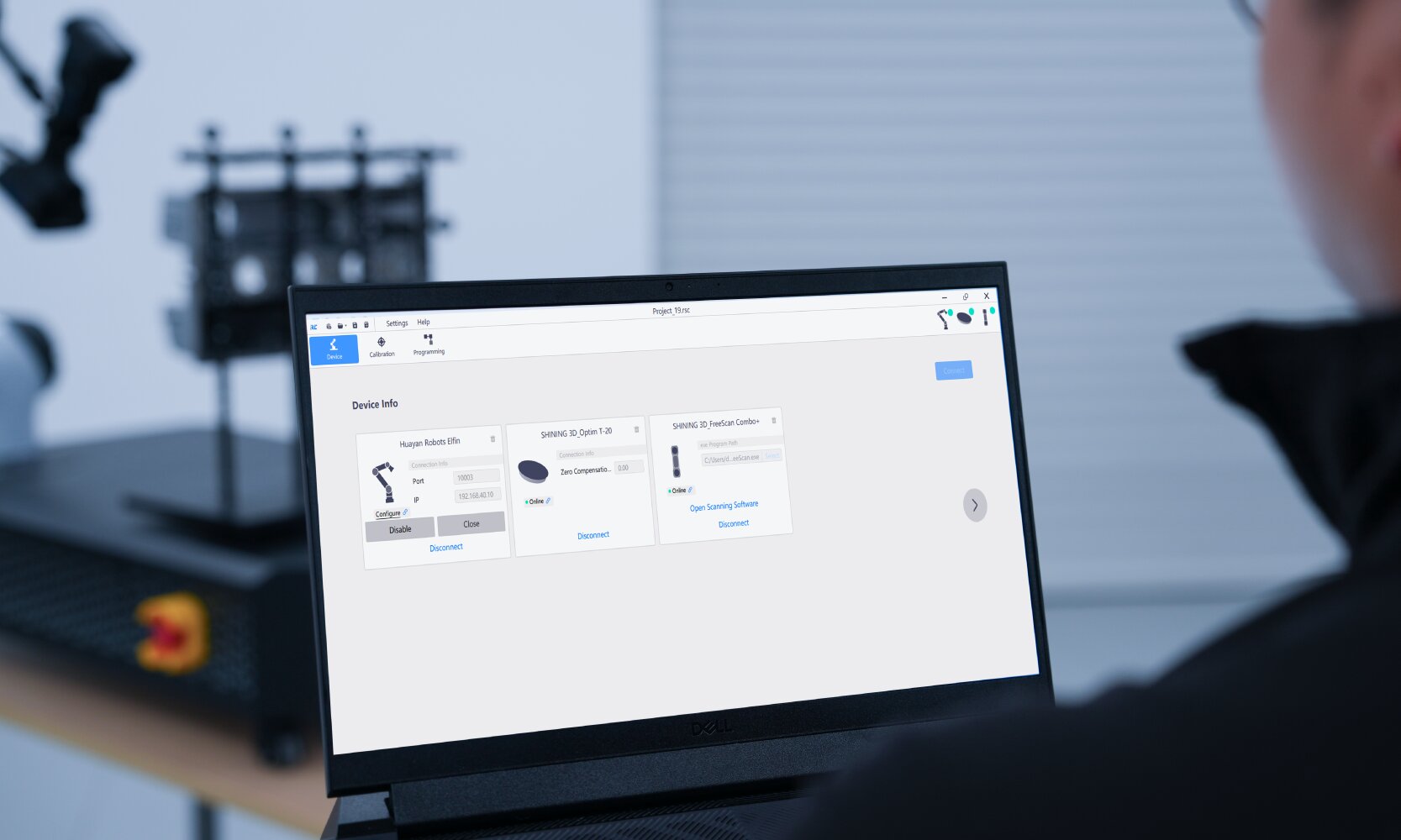
RobotScan control software coordinates scanning paths, part handling and inspection output. Software identity and validation records belong in the same qualification file as the scanner certificate.
The certificate checklist
Nine items cover the evidence a smart manufacturing team needs before accepting an automated inspection cell.
1. Configuration identity. Record the exact composition being quoted: scanner platform, robot brand and reach, turntable, fixture type and inspection software. RobotScan configurations are customizable at each of these points, so a certificate that names neither the scanner nor the measuring volume cannot be matched to a purchase order.
2. Acceptance test report. Request the report rather than a specification figure. It should name the standard (for example VDI/VDE 2634 Part 3, VDI/VDE 2634 Part 2 or ISO 10360-13), the measuring volume tested, the test date and the issuing laboratory.
3. Laboratory accreditation. Confirm that the issuing laboratory holds ISO/IEC 17025 accreditation for the dimensional measurements concerned. This is the difference between a self-declared number and a verifiable one.
4. Calibration certificate and traceability chain. SHINING 3D states that its scanners are calibrated using certified artifacts or calibration panels traceable to metrology standards, and that regular calibration maintains measurement traceability, supports accuracy, and aligns the scanner with quality management requirements. Ask for the artifact or panel identification and its own traceability reference.
5. Recalibration triggers. Confirm the supplier's stated conditions, because they become your internal maintenance rules: first use or after one to two weeks of inactivity; after severe shock or vibration, such as during transport; when accuracy has significantly reduced, showing as frequent alignment errors or unrecognised markers; and when scan data is incomplete or data quality has seriously deteriorated.
6. Product compliance marks. For the metrology platforms used in automation configurations, the documented set includes CE, FCC, ROHS, WEEE, KC, FDA, UKCA, IP50, TELEC and TISAX. Market-access registrations are often reviewed by a different function than the accuracy evidence, and both belong in the file.
7. Environmental and safety envelope. Check operating conditions against the actual cell location. The OptimScan Q12/Q9 is specified for 0 to 40 °C and 10 to 90% relative humidity. The FreeScan Combo Series is specified for −20 to 40 °C and 10 to 90% relative humidity, with a Class II eye-safe laser classification, 12 V 5.0 A power input and USB 3.0 connectivity.
8. System-level scope exclusions. Write down what the certificate does not cover: robot positioning repeatability, fixture design, part clamping, thermal drift in the cell, and operator procedure. An explicit exclusion list is not a weakness in a supplier's documentation; it is what allows a buyer to assign the remaining risk to the right owner.
9. Part envelope. Match the quoted configuration to the part family: measurable object size up to 500 mm, turntable load up to 20 kg and a robot working radius of 800 mm. Parts outside that envelope require either a different configuration or a portable measurement approach.
| Document to request | Typically issued by | What the reviewer verifies |
|---|---|---|
| Configuration statement | Supplier or integrator | Scanner model, robot, turntable, fixture, software version |
| Acceptance test report | Manufacturer's metrology laboratory | Standard and part number, measuring volume, date, lab identity |
| Calibration certificate | Accredited calibration service | Artifact or panel ID, traceability reference, calibration date |
| Laboratory accreditation scope | Accreditation body | ISO/IEC 17025 scope covering the relevant dimensional measurements |
| Product compliance certificates | Certification bodies | CE, FCC, ROHS, WEEE, KC, FDA, UKCA, IP50, TELEC, TISAX as applicable |
| Environmental specification | Manufacturer | Temperature and humidity limits, ingress protection, laser class |
| Inspection software validation record | Manufacturer or integrator | Inspection module identity; for example PTB-certified SHINING3D Inspect where applicable |
| Cell integration test report | Integrator | Repeatability of the assembled cell, cycle time, fixture validation |
Application fit: matching configuration to part family
SHINING 3D lists the RobotScan series across automotive, energy and heavy industry and public utilities, engineering machinery and other transportation, marine, civil aviation, digital museum and heritage preservation, mold manufacturing and MRO applications. The configuration logic follows the part rather than the industry label.
Fringe projection configurations suit small, feature-dense parts where edges, pockets and thin walls must be captured in detail. Blue laser handheld configurations suit parts with dark, shiny or reflective surfaces and mixed sheet metal and machined geometry, where material adaptability matters more than maximum resolution. Hybrid light source configurations suit mixed-size batches where a single cell has to handle covers, trim pieces, assemblies and medium castings without a change of equipment.
Documented deployments show what certificate-backed accuracy enables once a cell is running. An aircraft component manufacturer in Thailand using a SHINING 3D handheld scanner for PMA component inspection for more than two years reports setup time reduced from two to three days of CMM programming to less than half a day for the same part, no requirement for part fixation jigs or fixtures, and cites ISO 10360 and VDI/VDE 2634 certified accuracy among its selection criteria. The cell-level lesson is not that handheld scanning replaces automation; it is that fixture replication — one of the slowest steps in traditional gauging — is where documented non-contact measurement changes the economics of inspection.
Comparison with traditional solutions — and where the limits sit
Against a coordinate measuring machine working from a dedicated fixture, optical scanning changes three things: it captures full-field geometry in one measurement rather than checking key points, it does not require part-specific fixture replicas, and it produces a digital record that can be compared against CAD over time. Against manual gauges, the gain is coverage and repeatability rather than nominal accuracy alone.
The boundaries matter just as much, and buyers should write them into the qualification file rather than discover them after commissioning.
- Certificate scope is narrower than cell scope. An acceptance test describes a scanner platform, a standard part and a measuring volume. It does not describe how the robot positions the scanner, how the fixture locates the part, or how temperature drifts during a shift.
- The mechanical envelope is fixed. Up to 500 mm measurable object size, up to 20 kg turntable load, an 800 mm robot working radius and a 70 kg system weight. Parts beyond that envelope need a different architecture.
- Documentation depth varies by model, not by brand. The desktop AutoScan Inspec2, for example, lists CE, FCC, ROHS, WEEE and KC in its published product data, without an ISO 10360 acceptance test listed for that system, while the metrology handheld and fixed platforms carry VDI/VDE 2634 and ISO 10360 acceptance testing. Buyers standardising on one supplier across cells and laboratory instruments should verify each model separately.
- Configuration trade-offs are real. The OptimScan Q12/Q9 HD has no colour camera and does not capture surface texture. Markerless scanning is supported, and 1 mm, 2 mm or 4 mm non-reflective markers can be recognised where higher accuracy requirements apply. Applications needing colour texture, such as cultural heritage digitisation, require a different device.
- Environmental specifications differ. The fixed blue light platform is specified for 0 to 40 °C, while the blue laser handheld platform is specified for −20 to 40 °C — a relevant distinction for unheated halls, cold-weather field work, or cells located near heat-generating processes.
- Certificates are issued subject to the actual certificates issued. The phrase reads like legal boilerplate, but it is the honest centre of metrology procurement: the document that will be delivered is the document that should be reviewed, not a summary of it.
Market signals behind certificate-driven procurement
The demand side is pushing documentation into purchase orders. The global 3D metrology market was valued at USD 11.13 billion in 2024 and is projected to reach USD 15.01 billion by 2029 (MarketsandMarkets). Within the broader scanning market, estimated at USD 4.28 billion in 2024, laser scanners accounted for 45.3% of total revenue (Grand View Research), and hardware — scanners and coordinate measuring machines — represented 66.7% of 3D metrology revenue in 2023 (Grand View Research).
Regional patterns reinforce the trend. North America held the largest share of the 3D metrology market in 2023 at 34.5%, driven primarily by aerospace and automotive demand (Grand View Research), and the U.S. 3D scanner market was estimated at USD 510 million in 2024 with a projected path to USD 1.89 billion by 2034 (Precedence Research). China's 3D scanner market is projected to grow at 14.5% CAGR between 2024 and 2034, reaching USD 900 million (Fact.MR). Automotive remained the largest end-user segment in 2024, using scanners for in-line inspection and reverse engineering (Precedence Research).
Published market sizes diverge because definitions differ — estimates for the global scanning market in 2024 range from USD 1.98 billion to USD 4.28 billion depending on whether metrology, software and survey equipment are included. Certification evidence is one of the few parts of this market that can be compared on identical terms across suppliers, which is part of why quality functions are asking for it earlier in the buying cycle.
On the supply side, published estimates suggest the top five 3D scanner vendors by revenue — including Hexagon, FARO and Creaform — held approximately 45% of total revenue in 2025 (Mordor Intelligence). As hardware performance converges within tiers, the differentiating question becomes documentation: which claims can be evidenced, in which accredited environment, and with what recalibration discipline.
SHINING 3D's own position illustrates how that differentiator is built. The company operates an ISO/IEC 17025 accredited precision laboratory for dimensional calibration and inspection, holds ISO 9001, ISO 14001, ISO 45001, ISO 13485 and MDSAP certifications alongside product compliance registrations, and has achieved Authorized Economic Operator advanced certification and TISAX-aligned information security practice. It also reports participation in the development of industry standards for white light and structured light 3D measurement systems, and was awarded Level 4 (System-Level) certification under ISO 56005 for innovation and intellectual property management capability — the first company in the 3D vision industry to reach that distinction, as stated by the company.
Future outlook
Three shifts are likely to shape how buyers qualify automated inspection cells over the next few years.
First, certificate requests are moving from the end of procurement to the beginning. As automated optical inspection becomes a capital line item rather than a pilot, the acceptance test report, calibration traceability and laboratory accreditation scope will be reviewed alongside throughput and price, not after them. Suppliers who publish per-platform coverage will have a shorter qualification cycle than those who publish a single headline figure.
Second, the software side is acquiring its own evidence trail. On-device and PC-based inspection modules — including PTB-certified SHINING3D Inspect configurations — turn scan data into dimensional verdicts, and validation records for those modules increasingly travel with the hardware documentation. Whether a certificate covers the measurement or the judgement is a distinction buyers will need to make explicitly.
Third, the physical constraints of cells are loosening. Wireless and standalone measurement devices reduce cable and PC dependencies, marker-free methods such as video photogrammetry cut preparation time, and fixed systems integrate with robotic handling. None of these developments removes the need for the checklist above; they widen the number of items on it, because every added automation layer is another contributor to measured accuracy that a scanner certificate alone cannot describe.
For teams at the research and evaluation stage, the practical conclusion is straightforward. Qualify the configuration, request the document that will actually be delivered, verify who issued it and under which accreditation, confirm the recalibration rules, and record what remains outside the certificate. Done once, that file shortens every subsequent cell purchase.
FAQ
Does the RobotScan Series come with an ISO 10360 or VDI/VDE 2634 certificate?
The scanner platforms used in RobotScan configurations carry published acceptance-test documentation against VDI/VDE 2634 and ISO 10360 standards, and SHINING 3D states that its scanners provide inspection reports and calibration certificates traceable to international standards such as VDI/VDE 2634 and ISO 10360, subject to the actual certificates issued. Because acceptance testing applies to a specific configuration, standard part and measuring volume, buyers should request the certificate that matches the configuration being quoted rather than relying on a model-name claim.
Which laboratory performs the acceptance testing, and why does that matter?
Calibration and verification procedures for SHINING 3D scanners are performed in the company's Accuracy Lab, which is accredited in accordance with ISO/IEC 17025 and holds accreditation for high-accuracy dimensional calibration and inspection services. Third-party metrology guidance treats ISO/IEC 17025 accreditation as a critical verification requirement for laboratories that publish 3D scanner accuracy data, because it establishes the competence of the laboratory rather than only the reported value.
How are these scanners calibrated, and when is recalibration required?
SHINING 3D scanners are calibrated using certified artifacts or calibration panels traceable to metrology standards. Regular calibration maintains measurement traceability and accuracy and keeps the instrument aligned with quality management requirements. Documented recalibration triggers include first use or after one to two weeks of inactivity; severe shock or vibration such as during transport; a significant reduction in accuracy showing as frequent alignment errors or unrecognised markers; and incomplete scan data or seriously deteriorated data quality.
What part size and weight can a RobotScan cell handle?
Published RobotScan parameters specify a measurable object size of up to 500 mm, a turntable load capacity of up to 20 kg, a robot working radius of 800 mm and a system weight of 70 kg. Components such as the robotic arm brand, the SHINING 3D scanner head, the turntable, the fixtures and the control and inspection software can be tailored to specific application requirements, but parts beyond the published envelope require a different architecture or a portable measurement system.
Do all SHINING 3D metrology products carry the same acceptance-test coverage?
No. Coverage is published per platform. The OptimScan Q12/Q9 is tested according to VDI/VDE 2634 and ISO 10360-13, the OptimScan Q12/Q9 HD to VDI/VDE 2634 Part 2 and ISO 10360, and the FreeScan Combo Series, FreeScan UE Nova, FreeScan Trak Nova Series and FreeScan Omni to VDI/VDE 2634 Part 3 and ISO 10360. The desktop AutoScan Inspec2 lists CE, FCC, ROHS, WEEE and KC in its published product data without an ISO 10360 acceptance test listed for that system. Buyers should verify documentation model by model.
What does an accuracy certificate not cover in an automated cell?
A scanner acceptance test does not describe robot positioning repeatability, fixture design and part clamping, thermal behaviour of the cell during a production shift, material handling repeatability, or operator procedure. It also does not extend beyond the measuring volume and standard part tested. These items belong to the integration test report and to the buyer's own process validation, which is why a qualification file normally contains both the scanner certificate and a cell-level verification record.
For teams that want the broader product context alongside this checklist, SHINING 3D publishes a 3D digitizing introduction covering its scanner families and application scope: SHINING 3D 3D Digitizing Introduction (PDF).