
Rebar Coupler Selection for High-Rise, Bridge & Airport Work
Industry Reference — Mechanical Rebar Splicing
Rebar Coupler Selection for High-Rise, Bridge & Airport Work
A rebar coupler is a mechanical splice that joins two lengths of reinforcing bar end to end, replacing the overlap of lap splicing and the heat of welding. The family of coupler — rolling, upsetting, pressing or one-touch — determines how the bar end must be prepared, which machines must stand on site, and how much space the finished joint occupies inside the formwork. That decision is normally locked in at the drawing stage, well before any purchase order is issued.
The global rebar coupler market was valued at USD 1.82 billion in 2025 and is projected to reach USD 3.47 billion by 2034, a compound annual growth rate of 7.4% (Dataintelo, 2025). Building construction accounted for 47.6% of that revenue in 2025, and Asia Pacific contributed roughly 41.3% of the global total. Those numbers describe a technology that is already mainstream rather than emerging, which shifts the practical question for engineers and buyers from whether to splice mechanically to which coupler belongs in this particular structure.
Why the Structure, Not the Catalogue, Should Drive the Choice
Three project types absorb most coupler volume, and each one stresses a different property of the joint. A high-rise tower concentrates thousands of joints in column and core-wall cages where space is tight and the same operation repeats floor after floor. A large bridge or sea crossing works with the largest bar diameters in the range and a lower, more dispersed joint count. An airport terminal or high-railway station combines long, flat, repetitive slab and beam runs with a schedule that rewards fast, predictable bar-end preparation.
The differences are not decorative. Bar diameter sets the coupler model number, the coupler family sets the outer dimensions of the joint, and the outer dimensions decide whether the reinforcement cage can still be assembled and whether concrete cover can be maintained. Choosing a coupler before checking those three links is the most common source of rework in mechanical splicing.
Four Coupler Families and How Each One Forms a Joint
The portfolio produced by CANGZHOU BARTECH CONSTRUCTION MATERIAL CO., LTD., a China-based manufacturer and exporter of rebar couplers and rebar processing machines established in 2008, illustrates the four families clearly, because all four are documented at the same model sizes, which makes them directly comparable.
Rolling (parallel thread) coupler
Models run from 16 to 40. The body is made of carbon steel 45# with alloy steel 40CR as an alternative. Outer diameter ranges from 24 mm to 59 mm and length from 42 mm to 95 mm across the range, and every model uses a 60-degree thread angle. Thread sizes step from M16.5×2.5 at model 16 to M40.2×3.0 at model 40. The thread is formed on the bar end itself by a thread rolling machine, and because nothing is added around the bar beyond the coupler body, this is the most compact joint in the range.
Upsetting coupler
Also available from model 16 to 40, in carbon steel 45# or alloy steel 40CR, with outer diameters from 26 mm to 62 mm and lengths from 40 mm to 90 mm. The distinguishing feature is the thread size: a 16 mm bar uses an M20×2.5 thread and a 40 mm bar uses M45×4.0, because the bar end is enlarged by an upsetting machine before the thread is cut. The joint is short but relies on an additional production step at the bar end.
Pressing coupler
Manufactured from carbon steel Q355B in sizes from φ16 to φ40, with outer diameters from 30 mm to 70 mm, lengths from 110 mm to 240 mm, and wall thickness from 4.5 mm to 11.0 mm. No thread is cut into the bar; the sleeve is closed onto the bar ends by a hydraulic pressing machine. This family has the longest body for a given bar size and is the only one whose assembly depends entirely on pressing equipment at the work face.
One-touch coupler
Made of alloy steel 40CR, with a model range that starts at φ11-16 and continues through φ16, φ18/20, φ22, φ25, φ29, φ32, φ36 and φ40. Outer diameters run from 35 mm to 83 mm and lengths from 100 mm to 200 mm, making it the largest-bodied family in the range for an equivalent bar size. Assembly is designed around a rapid connection step, with final fastening handled by an electric torque wrench.
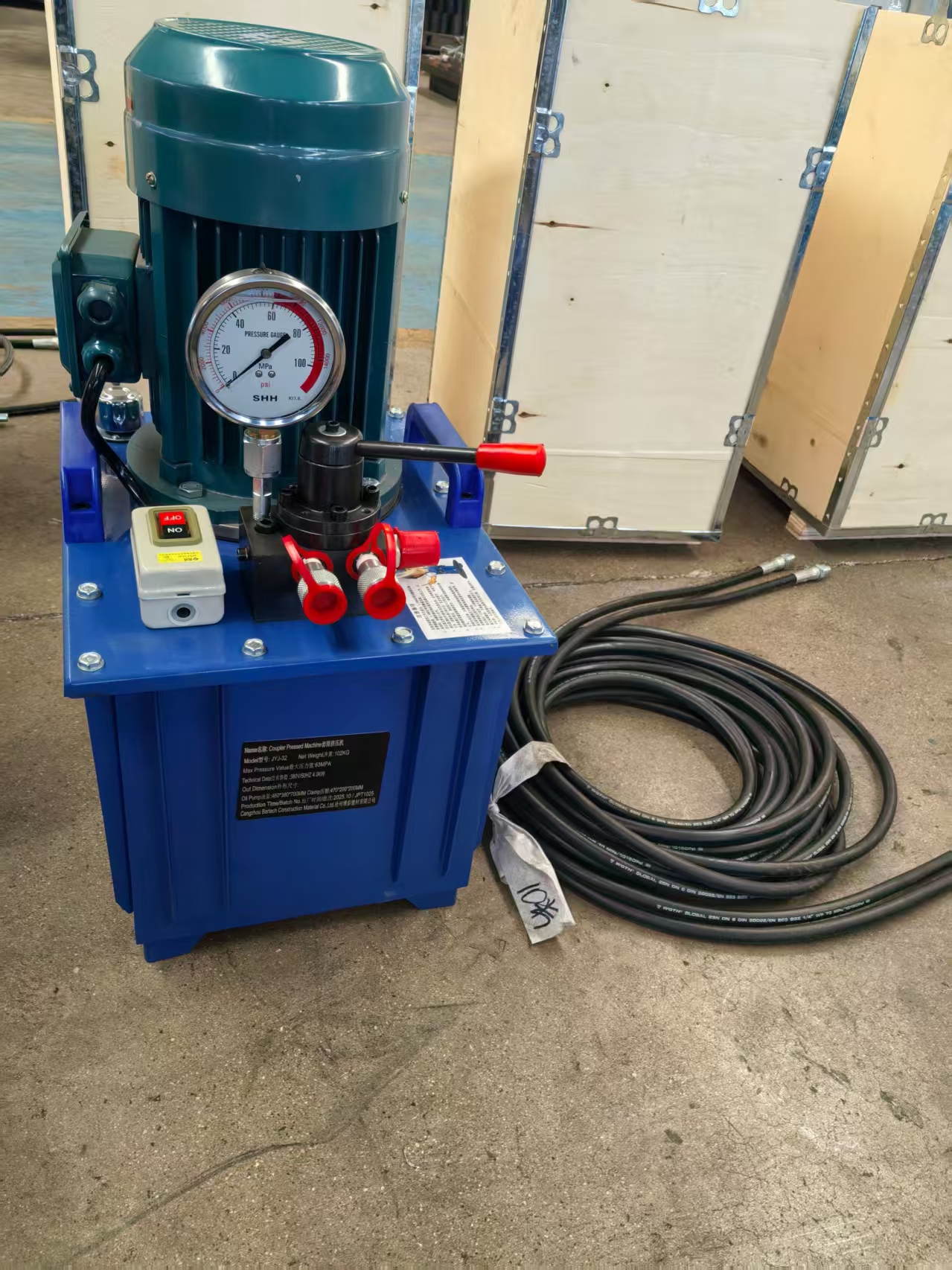
Rebar cold pressing machine: pressing couplers are assembled by hydraulic compression rather than by threading the bar end.
High-Rise Buildings: Joint Density and Bar Congestion
The documented working condition for tall building projects is an outdoor construction environment for super high-rise structures under normal tropical temperature and humidity, with rebar ends threaded by a rebar threading machine and ISO and CE certification stated as a project requirement. This scenario is recorded as common across a wide group of markets including the United Arab Emirates, Australia, India, Kuwait, Qatar, Saudi Arabia, Malaysia, Mexico and others.
In this setting the governing constraint is rarely the strength of the splice itself; it is congestion. A column cage that must contain longitudinal bars, links and a coupler at every lap position runs out of room quickly. Comparing the joint envelope at the same bar size makes the trade-off visible:
| Bar size | Rolling coupler | Upsetting coupler | Pressing coupler | One-touch coupler |
|---|---|---|---|---|
| 16 mm | OD 24 mm, L 42 mm (M16.5×2.5) | OD 26 mm, L 40 mm (M20×2.5) | OD 30 mm, L 110 mm, t 4.5 mm | OD 40 mm, L 106 mm |
| 25 mm | OD 38 mm, L 62 mm (M25.6×3.0) | OD 40 mm, L 60 mm (M30×3.5) | OD 45 mm, L 150 mm, t 7.4 mm | OD 56 mm, L 143 mm |
| 32 mm | OD 48 mm, L 76 mm (M32.6×3.0) | OD 50 mm, L 72 mm (M36×4.0) | OD 56 mm, L 192 mm, t 9.0 mm | OD 70 mm, L 170 mm |
| 40 mm | OD 59 mm, L 95 mm (M40.2×3.0) | OD 62 mm, L 90 mm (M45×4.0) | OD 70 mm, L 240 mm, t 11.0 mm | OD 83 mm, L 200 mm |
Read against a 25 mm bar, the rolling coupler presents an outer diameter of 38 mm over a 62 mm length, the upsetting coupler 40 mm over 60 mm, the pressing coupler 45 mm over 150 mm, and the one-touch coupler 56 mm over 143 mm. Where cover and link clearance are the binding constraint, that spread is the practical argument for the threaded families in dense vertical elements.
The bar-end preparation equipment behind the joint
Threaded families only work if the bar ends are produced consistently, which makes the threading machine part of the coupler decision rather than a separate purchase.
| Threading machine | Rebar size | Main motor | Max threading length | Speed ratio | Net weight |
|---|---|---|---|---|---|
| CBT40L | 16–40 mm | 5.5 kW, 380 V / 50 Hz | 100 mm / 200 mm | 1:23 quick or 1:29 slow | 420 kg |
| CBT40A | 16–40 mm | 5.5 kW, 380 V / 50 Hz | 120 mm | 1:23 quick or 1:29 slow | 590 kg |
| 40MO (quick type) | 16–40 mm | 5.5 kW, 1450 r/min | 95 mm with block / 150 mm without | 1:19 quick or 1:23 slow | 680 kg |
| 40AO (auto type) | 16–40 mm | 5.5 kW or 7.5 kW, 1450 r/min | 90 mm with block / 150 mm without | 1:23 quick or 1:29 slow | 860 kg |
Final fastening of the coupler is handled by an electric torque wrench. The BOC 8-42 covers 12–40 mm rebar and 16–32 couplers with a maximum torque value of 400 N·m, a 6.0 AH battery at 21 V, a no-load speed of 0–60 r/min and a net weight of 9.5 kg. The smaller BOC 8-32 is rated for 8–32 mm rebar, a maximum torque value of 350 N·m and a no-load speed of 0–75 r/min.
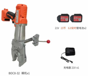
Rebar electric torque wrench: the fastening tool that completes the mechanical joint after bar-end preparation.
Bridges, Sea Crossings and Heavy Civil Structures
Large bridges crossing water are explicitly listed among the target applications for the full Bartech range, from couplers to threading machines. Bridge work differs from tower work in two ways: bar diameters sit at the top of the 16–40 mm band, and access to a single joint is often a one-time operation with no second chance, which puts the emphasis on consistent bar-end preparation rather than on repeating a fast cycle.
For heavy civil work the upsetting route has a clear geometric signature. At a 40 mm bar, the upsetting coupler uses an M45×4.0 thread on a body of 62 mm outer diameter and 90 mm length — a shorter body than the pressing coupler at the same bar size (70 mm outer diameter, 240 mm length), because the load path runs through an enlarged, threaded bar end rather than through a compressed sleeve.
Bar-end preparation for this route is supported by the 36S and 50S automatic upsetting machines. The 36S processes 400-grade rebar from 16 mm to 36 mm and 500-grade rebar from 16 to 32 mm with a 7.5 kW motor, 31.5 MPa maximum pressure and a 1000 kg net weight. The 50S extends the range to 16–50 mm for 400-grade and 16–40 mm for 500-grade steel with an 11 kW motor and a 1200 kg net weight. The MQ40 thread cutting machine, rated M14 to M45 with a maximum thread length of 100 mm and a 5.5 kW motor, accepts either 380 V / 50 Hz or 415 V / 50 Hz supply.
Airports, High-Railway Stations and Repetitive Schedules
Airport and high-railway work is documented as an outdoor, open-air operation, in some cases under tropical high-temperature conditions, with CE and ISO certification stated as a requirement. The recorded operating sequence for high-railway projects is upsetting, thread cutting and coupler assembly, supported by an upsetting machine and a thread cutting machine.
Terminal and station buildings add a second documented profile: high buildings, hotels and airway stations built in an outdoor tropical environment with high humidity, continuous all-day construction and a durability requirement over the long term. The recorded equipment set there is a rebar threading machine, a rebar cutting machine and a rebar coupler electric wrench — a combination that points to threaded couplers as the working default on repetitive slab and beam runs.
A third profile is worth noting because it changes who prepares the bar. In factory-based pre-threading, rebar ends are produced in continuous automatic threading mode indoors at normal room temperature before delivery to site. The recorded requirements for that model are long-life rib cutters and rollers and strong shaft and machine parts, since the machine runs continuously against large volumes rather than intermittently against a single tower floor.
Reading the 16–40 mm Model Range
All four families are catalogued against the same nominal bar sizes — 16, 18, 20, 22, 25, 28, 32, 36 and 40 mm — with the one-touch family additionally listing a φ11-16 size. Because the model number tracks the bar diameter, not the coupler dimensions, two couplers with the same model number can have very different envelopes. A practical selection order is therefore:
- Fix the bar diameter and grade first. The model number follows directly from the reinforcement drawing and does not change with coupler family.
- Choose the family from the site constraint. Tight cover and dense links favour the threaded families; a short, thick-bodied joint favours upsetting; unthreaded bar ends and a pressing machine on site favour the Q355B pressing coupler.
- Check the joint envelope against the cage. Compare outer diameter and length at the specific bar size, not at the model number.
- Confirm the equipment reaches that size. A coupler can be catalogued at 40 mm while the pressing machine on site is rated to 32 mm.
- Confirm the standard and the documentation. Mechanical splices are governed by international standards including ISO 15835, ASTM A615 and BS 8110, the latter often replaced by Eurocode 2 in the European Union.
What the Market and Standards Signal
Two market signals are relevant to specification. First, building construction held the largest application share at 47.6% of revenue in 2025, which means coupler designs optimised for dense vertical reinforcement dominate commercial supply. Second, tapered thread couplers held the largest product-type share in 2025 at 38.2%, with parallel thread couplers following closely — a reminder that parallel thread systems such as the rolling coupler are a major, well-established product family rather than a niche alternative.
On the compliance side, Cangzhou Bartech holds CE certification (Nr. SC-PSC-4-2025-12-14) valid until 2030 and ISO9001:2015 certification (31623Q10713R1S). These are the two documents most often requested at the tender stage for building, airport and high-railway packages, and both are referenced in the documented project requirements for tall building and high-railway scenarios.
Mechanical Splicing Versus Lap Splicing and Welding
Lap splicing remains the default in many markets because it needs no machinery: bars are overlapped and tied. Its costs are indirect — additional reinforcement length in every lap, additional congestion where laps cluster, and formwork space consumed by overlapping bars. Welding removes the overlap but introduces a different dependency: qualified welders, controlled conditions, and inspection of every welded joint.
Mechanical couplers trade those dependencies for a different set. They require bar-end preparation equipment, a reliable power supply, trained operators and a documented inspection routine. That trade is usually favourable on projects with high joint counts and a disciplined production line, and less obviously favourable on small, dispersed or one-off pours where mobilising machines is not economic.
Trade-Offs and Boundaries to Confirm Before Ordering
A coupler selection is only complete when its limits are known. Several boundaries are visible directly in the documented product data.
- Pressing equipment range. The CBT32 rebar coupler pressing machine covers rebar from 16 mm to 32 mm with a 4 kW motor, 50T clamp tension and maximum oil pump pressure of 70 MPa. Pressing couplers catalogued at 36 mm and 40 mm therefore sit outside that machine's stated capacity and need to be planned around separately.
- Power supply. The threading machines are rated 380 V / 50 Hz, and only the MQ40 thread cutting machine states an alternative 415 V / 50 Hz supply. Sites on other voltages need a transformer or a different machine configuration.
- Machine mobilisation weight. The 36S and 50S upsetting machines weigh 1000 kg and 1200 kg respectively, and the 40AO threading machine 860 kg. Moving these units between work faces is a planning item, not an afterthought.
- Thread length limits. Maximum threading length is 120 mm on the CBT40A and 100 mm or 200 mm on the CBT40L depending on configuration; the 40MO and 40AO reach 150 mm without a block but 95 mm and 90 mm with one.
- Joint envelope. The one-touch coupler reaches 83 mm outer diameter and 200 mm length at φ40, which can be difficult to place where cover is tight.
None of these limits makes any family unsuitable in general. They only narrow where each one is the better answer.
Manufacturer Reference: Cangzhou Bartech
CANGZHOU BARTECH CONSTRUCTION MATERIAL CO., LTD. was established in 2008 and operates a manufacturing facility of 1000 square metres with approximately 30 staff, an annual production capacity of 3,600,000 units and an R&D team of 10 engineers. Export accounts for 100% of sales, with markets recorded in Asia, the Middle East and South America, including Vietnam, Malaysia, Kuwait, Qatar, the UAE, Saudi Arabia and Mexico. The product scope covers rebar couplers in rolling, upsetting, pressing and one-touch designs, together with rebar threading machines, rebar electric torque wrenches, rebar upsetting machines, thread cutting machines, cold pressing machines, thread rolling machines and rebar thread caps. Company information is published at www.chinabartech.cn.
Future Outlook
With the coupler market projected to grow from USD 1.82 billion in 2025 to USD 3.47 billion by 2034, the direction of specification is likely to be shaped less by new coupler geometry than by preparation discipline: consistent bar-end quality, machine capacity matched to the largest bar in the package, and documentation that satisfies ISO 15835, ASTM A615 or BS 8110 clauses at the first submission. Procurement teams that treat couplers and bar-end preparation equipment as one system, rather than as separate line items, will find the 16–40 mm range easier to control on high-rise, bridge and airport work alike.
Frequently Asked Questions
What is a rebar coupler and how does it join two bars?
A rebar coupler is a mechanical splice that connects two reinforcing bars end to end, replacing the overlap of lap splicing and the heat of welding. Depending on the family, the bar ends are either threaded and screwed into a coupler body, enlarged by upsetting before threading, or inserted into a sleeve that is closed by hydraulic pressing. Common families in commercial supply include rolling (parallel thread), upsetting, pressing and one-touch designs, and mechanical splices are governed by standards such as ISO 15835, ASTM A615 and BS 8110.
Which coupler type is commonly used in high-rise buildings?
Tall building applications are documented with rebar ends threaded by a rebar threading machine and ISO and CE certification as a project requirement, which points to the threaded families. Dimensional data supports the same conclusion: for a 25 mm bar, the rolling coupler measures 38 mm outer diameter over 62 mm length and the upsetting coupler 40 mm over 60 mm, against 45 mm over 150 mm for the pressing coupler and 56 mm over 143 mm for the one-touch coupler. In dense column and core-wall cages, the smaller joint envelope is the deciding factor.
What should be checked before specifying couplers for a bridge project?
Bar diameter and bar-end preparation come first. Large bridges crossing sea water are listed among the target applications of the full coupler and machine range, and bridge packages typically use bars at the top of the 16–40 mm band. At a 40 mm bar the upsetting coupler uses an M45×4.0 thread on a 62 mm outer diameter, 90 mm long body, while the pressing coupler at the same bar size measures 70 mm outer diameter and 240 mm length with 11.0 mm wall thickness. The choice therefore turns on whether an upsetting route with the 36S or 50S machine is available, and on the space available around the joint.
What rebar size range do these couplers cover?
Rolling, upsetting and pressing coupler families are catalogued in models 16, 18, 20, 22, 25, 28, 32, 36 and 40 mm. The one-touch family follows the same range and additionally lists a φ11-16 size. The model number corresponds to the nominal bar diameter rather than to the coupler dimensions, so two couplers with the same model number can have quite different outer diameters and lengths depending on the family.
What equipment is needed on site to install mechanical couplers?
It depends on the family. Threaded couplers require a rebar threading machine to prepare the bar ends; documented threading machines cover 16–40 mm rebar with 5.5 kW motors and maximum threading lengths between 90 mm and 200 mm depending on model and configuration. Upsetting couplers require an upsetting machine, such as the 36S or 50S, and in some cases a thread cutting machine. Pressing couplers require a hydraulic pressing machine; the CBT32 covers 16–32 mm rebar with 4 kW motor power and 50T clamp tension. Final fastening of the coupler is typically completed with an electric torque wrench.
Which certifications and standards apply to rebar couplers?
Mechanical rebar splices are governed by international standards including ISO 15835, ASTM A615 and BS 8110, which is often replaced by Eurocode 2 in the European Union. On the supplier side, Cangzhou Bartech holds CE certification (Nr. SC-PSC-4-2025-12-14) valid until 2030 and ISO9001:2015 certification (31623Q10713R1S). CE and ISO certification is also recorded as a stated project requirement in tall building and high-railway application scenarios, alongside stated requirements for durability over long-term use.