
Rebar Coupler Thread FAQ: Sizes and Angles, M16.5 to M40
A rebar coupler succeeds or fails at a single interface: the thread that locks the bar end into the sleeve. Body length, wall thickness and material grade all exist to support that interface. When a mechanical splice fails an inspection on site, the cause is usually not the steel — it is a thread that was cut to the wrong length, matched to the wrong bar, or assembled without the two bar ends meeting inside the coupler.
This reference answers the technical thread questions we receive most often from engineers, detailers and procurement specialists working across the 16 mm to 40 mm rebar range. It uses the published dimensions and material designations of Cangzhou Bartech Construction Material Co., Ltd., a China-based manufacturer and exporter of rebar couplers, rebar threading machines and rebar electric wrenches. Founded in 2008 with a 1,000 m² factory and a 10-engineer R&D team, the company exports 100% of its output to markets including Vietnam, Malaysia, Kuwait, Qatar, the UAE, Saudi Arabia and Mexico.
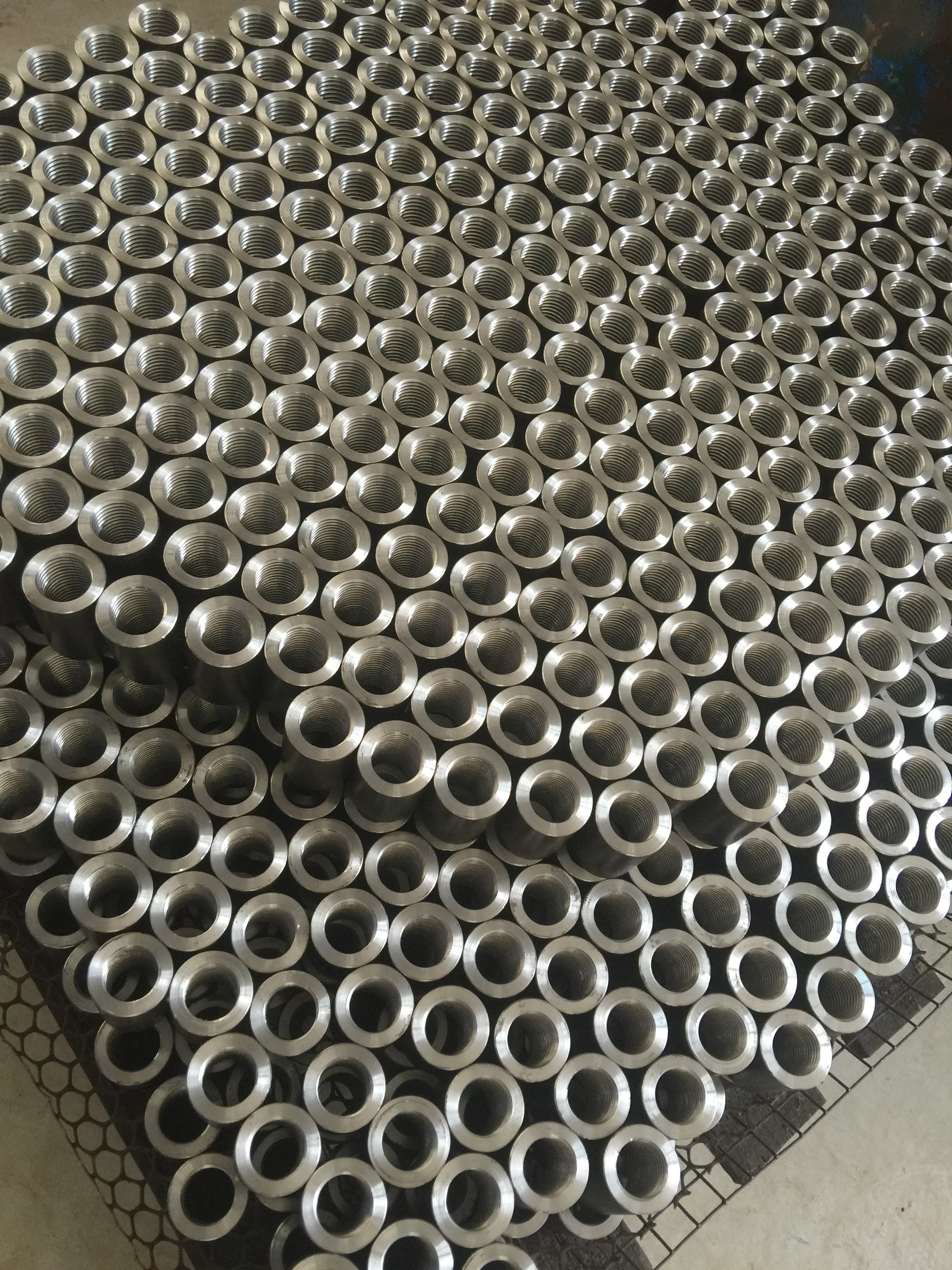
A parallel thread rebar coupler. The thread designation — not the outer diameter — defines what bar the sleeve will accept.
Why thread specification belongs in the procurement file
Two couplers can look identical from the outside and still be incompatible. A sleeve with a 30 mm outer diameter and a 110 mm length tells a buyer only that it is built for a φ16 bar; it says nothing about the thread cut inside it, the pitch, or the profile angle. That is why thread data has to be requested explicitly rather than inferred from the coupler body.
The practical consequence is downstream. If the supplier's thread designation does not match the threading machine and the thread-cutting programme used on site, the bar ends will not seat to the required depth, and the splice will be rejected during inspection. For a procurement team, the thread specification is therefore a compatibility document, not a marketing line. It has to travel together with the coupler order, the threading equipment order, and the operator instructions.
What a coupler model number actually represents
In the Bartech coupler family, the model designation tracks the nominal rebar size it is built for. The series covers sizes 16, 18, 20, 22, 25, 28, 32, 36 and 40. A “model 16” coupler is designed around a φ16 bar; a “model 40” coupler is designed around a φ40 bar.
The model number is a bar-size reference, not a thread call-out. It tells an engineer which bar diameter the sleeve is dimensioned for. The thread that is machined into it is a separate specification and, for the smallest model in the range, is expressed as M16.5 × 2.5. Buyers who treat the model number and the thread designation as interchangeable are the ones most likely to order the wrong threading programme.
Coupler body dimensions across the 16–40 mm range
The table below lists the published body dimensions for the coupler series, from φ16 to φ40. These figures are useful for two procurement tasks: confirming that the sleeve will fit within the detailing envelope and the concrete cover available at the joint, and verifying that a delivered batch matches the ordered model.
| Rebar size (model) | Coupler outer diameter | Coupler length | Wall thickness |
|---|---|---|---|
| φ16 | 30 mm | 110 mm | 4.5 mm |
| φ18 | 34 mm | 120 mm | 5.4 mm |
| φ20 | 36 mm | 120 mm | 5.5 mm |
| φ22 | 40 mm | 132 mm | 6.4 mm |
| φ25 | 45 mm | 150 mm | 7.4 mm |
| φ28 | 50 mm | 168 mm | 8.0 mm |
| φ32 | 56 mm | 192 mm | 9.0 mm |
| φ36 | 63.2 mm | 220 mm | 11.3 mm |
| φ40 | 70 mm | 240 mm | 11.0 mm |
Published coupler body dimensions for the 16–40 mm series. Body geometry changes with bar size; the thread designation is specified separately.
Reading a thread designation: what M16.5 × 2.5 means
The thread used on the smallest threaded coupler in this family is designated M16.5 × 2.5. Read it in three parts. The “M” identifies a metric thread profile. The “16.5” is the nominal thread diameter in millimetres. The “2.5” is the thread pitch — the axial distance between adjacent thread crests — in millimetres.
The single most common misreading is to assume that M16.5 means a 16.5 mm bar. It does not. The figure describes the thread itself, which is machined onto the prepared end of a φ16 bar. A designer should never substitute the thread designation for the bar call-out on a drawing, and a site team should never assume that any metric thread of the same nominal diameter will mate correctly with a given coupler.
The same logic extends up the range. Threaded models in this family span the M16.5 to M40 designation band, matched to rebar sizes 16 through 40. Because the designation scales with bar size, the practical rule for procurement is straightforward: order the coupler model and the threading programme as a matched pair, and confirm the thread call-out on the supplier's data sheet before releasing the order.
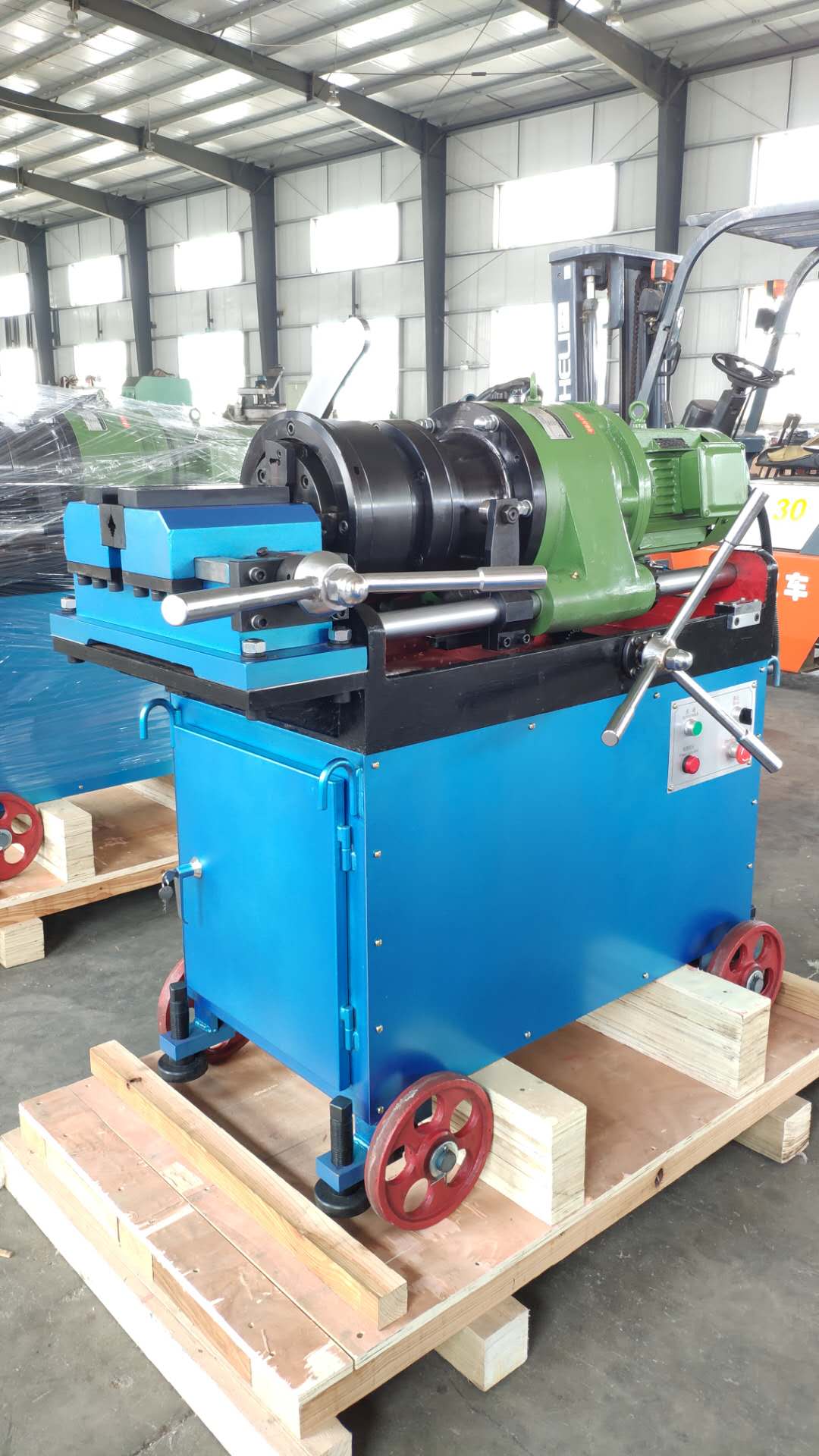
A rebar thread rolling machine forming the parallel thread that the coupler will receive.
The 60-degree thread angle and why it matters
Parallel thread rebar couplers use a 60-degree thread angle — the profile angle of the metric thread form. That angle is not an arbitrary manufacturing choice. It defines how the flank of the bar thread meets the flank of the coupler thread, and therefore how the axial load of the bar is transferred into the sleeve.
Three consequences follow for engineers and buyers:
- Contact is distributed across the flank. A 60-degree profile produces a wider load-bearing contact than a shallower angle, which spreads stress over more of the engaged thread length rather than concentrating it at the crest.
- The angle must match on both sides. A coupler machined to a 60-degree profile requires a bar thread of the same profile. Mixing thread forms — or mixing couplers and threading inserts from different programmes — is a compatibility failure, not a tolerance issue.
- Assembly depth becomes measurable. Because the profile is defined rather than approximate, the correct threading length and the correct wrenching depth can both be specified and checked.
In practice, the 60-degree angle is what makes the connection verifiable. It gives the inspector a defined geometric reference, which is exactly what a project specification needs in order to accept or reject a completed splice.
How the thread is produced: rolling, cutting and upsetting
A coupler is only half of the thread system. The other half is created on site or in a fabrication yard by the threading method the project has chosen. The three routes differ in equipment, in the bar end preparation they require, and in the range of bar sizes they serve.
Parallel thread rolling forms the thread by displacing material rather than removing it. It is the technology behind the standard parallel thread coupler family. Thread cutting machines the thread by removing material and is typically used where a cut thread profile is specified. Parallel thread upsetting enlarges the bar end before threading, which allows a full-strength thread on bars where direct threading would reduce the section.
Equipment capacity is the practical constraint that decides which route a project can use. The published specification for the 50S rebar upsetting machine illustrates the scale involved: a net weight of 1,200 kg, overall dimensions of 1,350 mm × 950 mm × 1,750 mm, rated voltage of 380 V / 50 Hz, main motor power of 11 kW, maximum pressure of 31.5 MPa, and an oil pump flux of 16 ml/r. It processes rebar sizes 16–50 mm for 400 rebar and 16–40 mm for 500 rebar.
For the rolling route, the CBT40A rebar threading machine is rated at 5.5 kW and supports rebar sizes from 16 mm to 40 mm — the same range covered by the coupler family. This alignment matters at the specification stage: a buyer who selects couplers across 16–40 mm should confirm that the threading machine offered alongside them covers the identical range, otherwise the upper or lower end of the project will need a second machine or an outsourced threading operation.
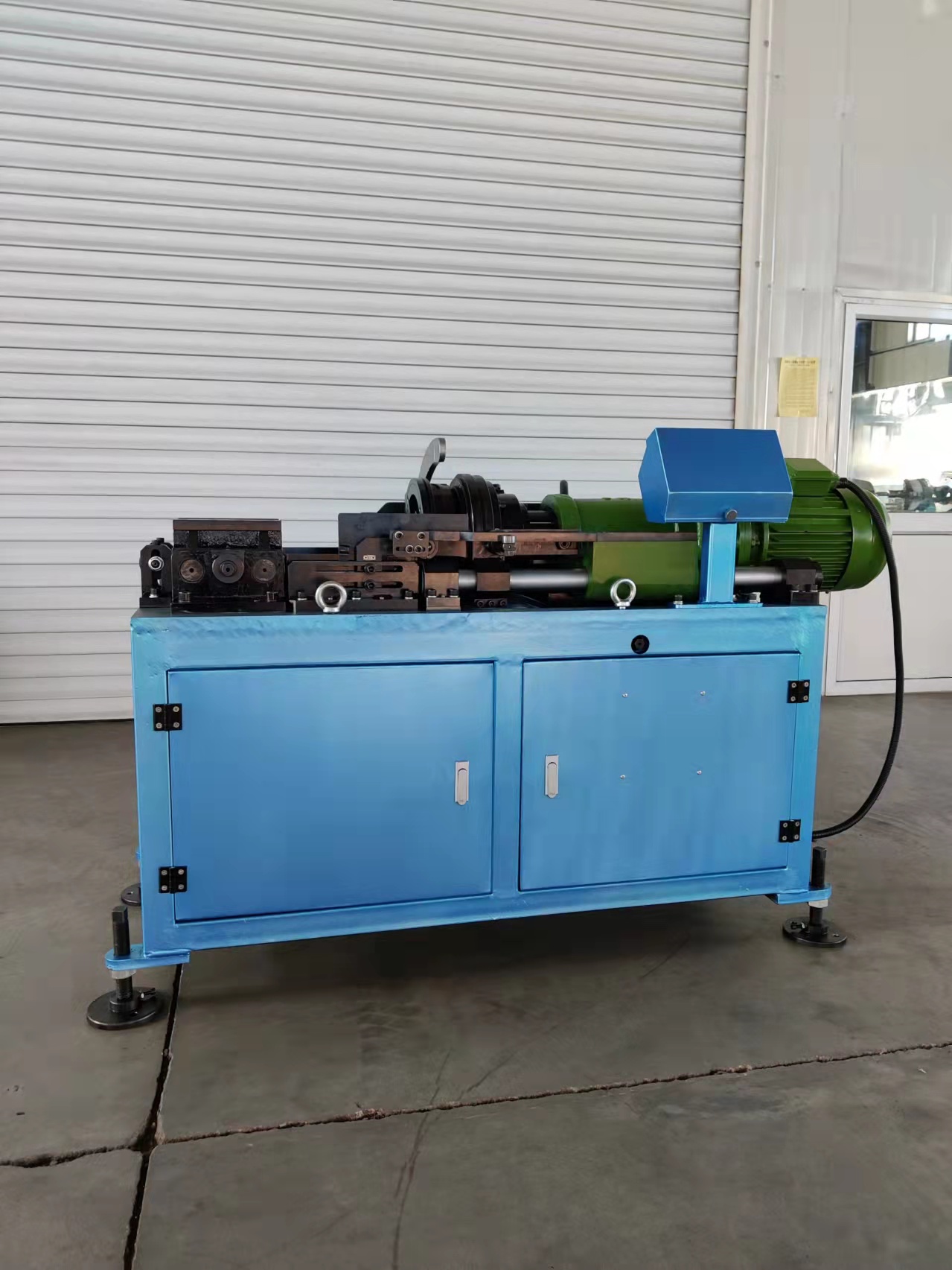
Thread preparation equipment on the bar-end side of the splice. Machine range and coupler range must match.
Where threaded couplers fit: project types
Threaded mechanical splices are specified across a recognised set of construction scenarios: high-rise buildings, airport projects, high-railway stations, large bridges and cross-sea bridges. Industries and projects that depend on these couplers include general construction, metro and tunnel works, and heavy infrastructure where continuous reinforcement cages are difficult to lap conventionally.
The reason these project types converge on threaded couplers is not only strength. In a high-rise core, a tunnel lining or a cross-sea bridge pier, the splice must be repeatable by a site crew working to a defined procedure. A 60-degree parallel thread with a fixed pitch and a defined assembly depth is repeatable in a way that a site-applied weld or a lap length is not.
Material selection also tracks the application. The ONE-TOUCH rebar coupler series, intended for the construction industry and used in high-rise, airport, high-railway station and large bridge scenarios, covers sizes 16 through 40 and is made of alloy steel 40CR. The rebar pressing coupler series covers the same 16–40 size range and is made of carbon steel Q355B — for example, the φ16 pressing coupler has a 30 mm outer diameter, 110 mm length and 4.5 mm thickness, while the φ40 unit measures 70 mm outer diameter, 240 mm length and 11.0 mm thickness.
Market context: why thread-standardised couplers are growing
The commercial environment supports the technical argument. The global rebar coupler market was valued at USD 1.82 billion in 2025 and is projected to reach USD 3.47 billion by 2034, a compound annual growth rate of 7.4%, according to Dataintelo. Building construction represented the dominant application, accounting for 47.6% of total revenue in 2025, and Asia Pacific was the largest regional market at approximately 41.3% of global revenue in the same year.
Product mix is also relevant to a thread-focused buyer. Tapered thread couplers held the largest product-type share in 2025 at 38.2%, with parallel thread couplers following closely behind. The two families are not interchangeable, since the thread forms differ, so a specification that names one form cannot be substituted with the other without re-checking the bar-end preparation, the threading programme and the assembly procedure.
Threaded couplers vs. lap splicing and welding — including the limits
Compared with traditional on-site rebar lap binding, mechanical couplers offer 50%–70% lower cost, easier operation and better quality control. Installation speed is 3–5 times faster than lap tying, and factory pre-threading results in on-site installation 2–4 times faster than welding. Compared with welding specifically, they are not affected by weather conditions, deliver 50% lower worker cost, and are easier to install and to quality-control.
Those numbers describe an established, repeatable process — not an unconditional advantage. The boundary condition is assembly discipline. A threaded connection is only sound if the bar ends are threaded to the correct length and wrenched so that the two bar ends meet each other inside the middle of the coupler. If the bars are not driven to the middle of the sleeve, the connection will not be correctly formed, and the splice will not deliver the performance the coupler is capable of.
That single requirement changes how a project has to be organised. Lap tying tolerates variable workmanship within a wide band; a threaded mechanical splice is far less forgiving, because the failure mode is invisible once the cage is closed. Procurement teams evaluating couplers against traditional methods should weigh this explicitly: the labour-cost saving depends on operators who thread to the correct length and wrench to the correct depth, every time. Suppliers mitigate this by issuing detailed operation documents and providing operator training, and both should be confirmed in the supplier evaluation rather than assumed.
Standards, certification and what to verify before ordering
Mechanical rebar splices are governed by international standards including ISO 15835, ASTM A615 and BS 8110, the latter often replaced by Eurocode 2 in the EU. These standards define the framework against which a splice system is qualified, and they are the reference a project specification will normally cite.
Supplier-level certification is a separate question from standard compliance and should be verified independently. Cangzhou Bartech Construction Material Co., Ltd. holds CE certification (Nr. SC-PSC-4-2025-12-14) valid until 2030 and ISO9001:2015 (31623Q10713R1S). A buyer assembling a technical file for a threaded coupler programme should hold three documents together: the coupler thread designation, the threading machine specification for the same bar-size range, and the supplier's certification evidence.
Future outlook
The direction of travel is toward tighter thread specification rather than looser. As mechanical splicing continues to move from premium projects into mainstream building construction — the segment that already accounts for 47.6% of coupler revenue — the practical pressure shifts from “does a coupler exist for this bar” to “is the thread call-out, the threading programme and the assembly depth all documented and checked”. Buyers who standardise thread designations across a project portfolio, and who require matched threading equipment with every coupler order, will spend less time resolving rejected splices on site. The M16.5 to M40 band, covering the overwhelming majority of reinforcement in commercial and infrastructure work, is where that standardisation effort delivers the most return.
Frequently asked technical questions
1. What thread size does a coupler use for 16 mm rebar?
The φ16 threaded coupler is matched to an M16.5 × 2.5 thread — a nominal thread diameter of 16.5 mm and a pitch of 2.5 mm. The coupler body for this model has a 30 mm outer diameter, a 110 mm length and a 4.5 mm wall thickness. Threaded models in the family span the M16.5 to M40 designation band, matched to rebar sizes 16 through 40.
2. Does M16.5 mean the coupler fits a 16.5 mm bar?
No. The “M16.5” component of the designation describes the thread, not the bar. It is the nominal diameter of the thread machined onto the prepared end of a φ16 bar. The coupler model number and the thread designation are two separate specifications and should both be confirmed on the supplier data sheet before ordering.
3. What is the thread angle on a parallel thread rebar coupler?
Parallel thread rebar couplers use a 60-degree thread angle, the profile angle of the metric thread form. The angle determines how the flank of the bar thread engages the flank of the coupler thread, distributing axial load across the engaged thread length rather than concentrating it at the crest. Both the coupler thread and the bar thread must carry the same 60-degree profile.
4. How do I know a threaded splice has been assembled correctly?
Two conditions must both be met. First, the bar end must be threaded to the correct length. Second, the two bar ends must be wrenched until they meet each other inside the middle of the coupler. If the bars are not wound into the middle of the coupler, the connection will not be properly formed. Suppliers support this by issuing detailed operation documents and providing operator training.
5. What equipment is needed to produce the matching bar thread?
It depends on the thread route. The CBT40A rebar threading machine is rated at 5.5 kW and supports rebar sizes from 16 mm to 40 mm. For upsetting, the 50S rebar upsetting machine has a net weight of 1,200 kg, dimensions of 1,350 mm × 950 mm × 1,750 mm, a rated voltage of 380 V / 50 Hz, 11 kW main motor power, 31.5 MPa maximum pressure and 16 ml/r oil pump flux; it processes 16–50 mm for 400 rebar and 16–40 mm for 500 rebar. The equipment range should be matched to the coupler range before ordering.
6. What materials are the couplers made from?
The ONE-TOUCH rebar coupler series, which covers sizes 16 through 40 and is used in high-rise, airport, high-railway station and large bridge scenarios, is made of alloy steel 40CR. The rebar pressing coupler series covers the same 16–40 size range and is made of carbon steel Q355B.
7. Which standards govern mechanical rebar splices?
Mechanical rebar splices are governed by international standards including ISO 15835, ASTM A615 and BS 8110, with BS 8110 often replaced by Eurocode 2 in the EU. Supplier certification is a separate check: Cangzhou Bartech Construction Material Co., Ltd. holds CE certification (Nr. SC-PSC-4-2025-12-14) valid until 2030 and ISO9001:2015 (31623Q10713R1S).
8. How do threaded couplers compare with lap tying and welding on cost and speed?
Against traditional on-site lap binding, couplers offer 50%–70% lower cost, easier operation and better quality control, with installation 3–5 times faster than lap tying. Against welding, on-site installation is 2–4 times faster, worker cost is 50% lower, and the process is not affected by weather conditions. The offsetting requirement is assembly discipline: bar ends must be threaded to the correct length and wrenched to meet in the middle of the coupler.
9. Which projects are threaded couplers typically specified for?
Common application scenarios include high-rise buildings, airport projects, high-railway stations, large bridges and cross-sea bridges, as well as metro and tunnel works and general construction where continuous reinforcement cages make conventional lapping impractical.
10. Are parallel thread and tapered thread couplers interchangeable?
No. They use different thread forms, so the bar-end preparation, threading programme and assembly procedure differ accordingly. In 2025, tapered thread couplers held the largest product-type share at 38.2%, with parallel thread couplers following closely behind — but a specification that names one form cannot be substituted with the other without re-validating the whole thread system.