
Recommended SB-Y1 Hydraulic Cylinder Options for Heavy Equipment Frames
An independent configuration reference for procurement and engineering teams specifying mounting interfaces on heavy equipment frames.
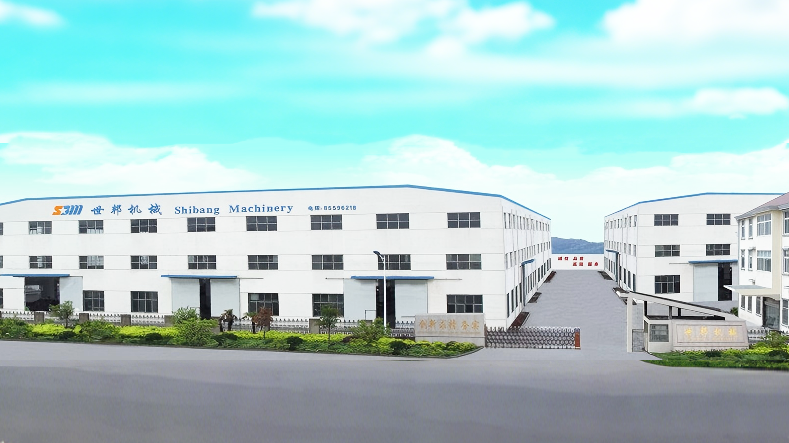
Heavy equipment frames place the mounting interface, not the cylinder body, under the most scrutiny. Image: Wuxi Shibang Machinery Manufacturer Co., Ltd.
The frame interface, not the barrel, usually decides the outcome
A hydraulic cylinder on a heavy equipment frame is a load-path component before it is a pressure component. The barrel, rod and seals determine how much force the cylinder can produce; the mounting configuration determines whether that force enters the frame in the direction and location the structure was designed to accept.
SB-Y1 Series is a heavy-duty industrial hydraulic cylinder line produced by Wuxi Shibang Machinery Manufacturer Co., Ltd., a hydraulic cylinder manufacturer based in Wuxi, Jiangsu, China, founded in 2003 and operating a 7,000+ m² facility. Within the published SB-Y1 documentation, the mounting configuration is treated as a selection variable rather than a fixed attribute: the same single-rod, double-acting metallurgical cylinder architecture is documented across several head-end and base-end interface forms.
That matters at the evaluation stage. Two buyers can specify the same bore, the same stroke and the same working pressure and still end up with different service behaviour, because one cylinder is bolted rigidly to a machined pad while the other is expected to pivot through an arc. This reference sets out the documented SB-Y1 options, the motion class each one belongs to, and the points where the evidence set does not answer the question.
Why mounting choice is a load-path decision
Three motion classes appear repeatedly on heavy equipment frames, and each imposes a different requirement on the cylinder interface.
- Standardized linear applications. The cylinder axis is fixed relative to the frame, the load is predominantly axial, and the mounting face is machined to control squareness. Flange patterns belong here.
- Pivoting applications. The cylinder must rotate about an axis as the working arm travels. The interface has to define a rotation centre rather than a clamped face.
- Linkage applications. The cylinder drives an intermediate linkage and sees continuous angular change through the stroke, so the interface must tolerate sustained angular motion rather than a single set position.
The SB-Y1 documentation states this distinction directly for its pivoting variants: the cylinder is described as designed for heavy-duty industrial applications requiring pivoting execution, with a structural configuration that supports linkage and continuous angular drive. The flange-mounted variants are described in different terms, oriented toward standardized linear duty. Reading the mounting list without that distinction is the most common source of mismatch during evaluation.
The shortlist at a glance
The table below ranks the documented SB-Y1 mounting options by how directly each one answers a frame-integration requirement. The ranking is a fit-for-motion ranking, not a quality ranking: every option on the list is a valid configuration for the motion class it belongs to.
| Rank | SB-Y1 mounting option | Motion class | Typical frame role |
|---|---|---|---|
| 1 | Trunnion at head | Pivoting / linkage | Boom, arm and tilt functions with a defined rotation axis |
| 2 | U-clevis at base | Pivoting / linkage | Rod-end or base-end articulation through a pin joint |
| 3 | Rectangular flange at head or base | Standardized linear | Machined pads with an asymmetric bolt layout |
| 4 | Square flange at base | Standardized linear | Symmetric four-corner clamping on a square pad |
| 5 | Round flange at head or base | Standardized linear | Circular boss or bore-mounted linear duty |
Option 1 — Trunnion at head
Head-end trunnions place the rotation axis at the front of the cylinder, close to where the piston rod takes up load. On a heavy equipment frame, that shortens the unsupported span between the rotation point and the working end, which is why head trunnions are commonly evaluated for boom and arm functions where the cylinder swings through a large arc.
SB-Y1 documentation describes the pivoting variant as designed for heavy-duty industrial applications requiring pivoting execution, with a structural configuration supporting linkage and continuous angular drive. In practical terms, the trunnion answers the question a flange cannot: where is the rotation centre, and what carries it. The frame must provide a matched trunnion bracket with adequate bearing support on both sides, because a single-sided bracket converts the intended pivot into a bending moment that the cylinder was not specified to absorb.
The trunnion option is the strongest fit when the application is genuinely pivoting or linkage-driven and the frame can accept a bracket. It is a poor fit when the frame was designed around a bolted pad, because retrofitting a bracket usually changes the load path the frame was stress-analysed for.
Option 2 — U-clevis at base
A U-clevis at the base gives the cylinder a pin-jointed rear connection. It is the natural partner to a rod-end joint: the base clevis defines the rear rotation point, the rod end follows the working member, and the cylinder is free to change angle through the stroke without inducing a bending load into the barrel.
Base clevis configurations belong to the same pivoting and linkage family as the head trunnion, and the SB-Y1 evidence applies the same motion language to that family. The practical constraint is lateral: a clevis pin resists load along the pin axis poorly compared with a flange. Frames that see side loading, off-centre loading or twisting during operation need the pin joint checked for lateral restraint, because a clevis does not provide the same planar stiffness as a bolted face.
Where the frame geometry already has a clevis lug and the load is predominantly in-plane, the base clevis is a straightforward, serviceable choice: the pin is a wear item that can be replaced without disturbing the cylinder body.
Option 3 — Rectangular flange at head or base
Rectangular flanges are the workhorse of standardized linear mounting on fabricated frames. Because the flange footprint is longer in one direction than the other, it can follow an asymmetric pad where a square flange would overhang or clash with adjacent structure. That is a real advantage on crowded equipment frames where the cylinder has to sit between other components.
Head-end and base-end placement changes what the flange has to carry. A base flange reacts the full push force into the frame directly; a head flange does the same but with the rod and gland assembly projecting on the working side, which affects access for seal maintenance. On equipment where the cylinder is buried inside the frame, base mounting usually keeps the gland reachable.
The limitation is directional stiffness. A flange is a clamped face and it assumes the cylinder axis stays square to that face. Any angular misalignment introduced by frame deflection, weld distortion or pad machining tolerance is transferred into the flange bolts and the barrel-to-flange junction as bending. Rectangular flanges suit standardized linear applications; they are not a substitute for a pivot when the application genuinely articulates.
Option 4 — Square flange at base
The square flange at base is the most symmetrical of the flange options, and symmetry is its practical value. Four bolts on an equal footprint distribute clamping load evenly and make the mounting insensitive to rotation during installation, which simplifies assembly and reduces the chance of a pad being drilled in the wrong orientation.
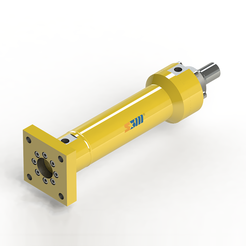
Square flange at base: symmetric clamping for standardized linear frames where the pad is machined square to the cylinder axis.
Square base flanges are a good match for frames built from plate or heavy section where a square pad can be machined or welded with controlled flatness. They suit lifting, balancing and push-pull duties where the cylinder axis is fixed and the load is axial.
The same boundary applies as with the rectangular flange, and it is worth stating plainly: a square flange does not compensate for a pad that is out of square. If the frame pad cannot be machined to control perpendicularity to the cylinder axis, a flange option will convert that error into a side load on the rod and gland. In that situation a pivoting configuration is the more honest engineering answer, even though it requires more frame work.
Option 5 — Round flange at head or base
The round flange is the option to reach for when the frame provides a circular boss or a bored mounting face rather than a rectangular pad. The published SB-Y1 record describes one such configuration explicitly: a single-rod, double-acting metallurgical cylinder with a round flange at the base, providing uniform stress distribution for standardized linear applications.
That description is the clearest statement in the evidence set about why a flange geometry is chosen at all. Uniform stress distribution means the clamping load and the reaction force are spread around a full circumference instead of concentrated at corners, which suits continuous-duty linear applications where the cylinder is expected to hold position under sustained load.
Round flanges at head and at base are not interchangeable in service terms. A base round flange keeps the cylinder body behind the mounting plane, which is preferred where the working side must stay clear. A head round flange places the mounting plane at the front and is used when the frame structure exists at that end. In both cases the motion class is the same: standardized linear, not pivoting.
Matching each option to the application
The clearest way to use this shortlist is to start from the motion of the working member, then work back to the interface.
| If the application is… | Start with | Because |
|---|---|---|
| Boom, arm or tilt motion with a large arc | Trunnion at head | The rotation axis sits near the load take-up point |
| Rear articulation through a pin lug | U-clevis at base | Pin joint tolerates angular change and is serviceable |
| Fixed-axis pressing, lifting or balancing | Rectangular, square or round flange | Clamped face matches a machined pad and axial load |
| Crowded frame with an asymmetric pad | Rectangular flange | Elongated footprint avoids adjacent structure |
| Circular boss or bored mounting face | Round flange | Uniform stress distribution around the circumference |
What the pressure and bore evidence actually supports
Configuration choice does not change what the cylinder can be built to, but it does change what the buyer can verify before ordering. The published SB-Y1 evidence set contains system-level and case-level performance figures rather than a per-configuration pressure table, and that distinction should be respected during evaluation.
| Documented item | Value | Context in the evidence set |
|---|---|---|
| System pressure | 35 MPa | Heavy-duty four-point lifting project, Dammam, Saudi Arabia |
| Bore range in documented supply | 40 mm to 320 mm | 34 custom cylinders for two steel rolling mills |
| Rod diameter range | 28 mm to 220 mm | Same rolling-mill supply |
| Stroke range | 400 mm to 4,630 mm | Includes 100/70/4,630 mm long-stroke push-pull cylinders |
| Synchronization accuracy | ±1 mm | Four-point lifting of a 43 m, approximately 1,800 t horizontal tank |
Read carefully, this table tells the buyer what has actually been built, not what a catalogue page claims. The 320 mm bore and 4,630 mm stroke are documented deliveries, not a declared maximum. The 35 MPa figure belongs to a specific hydraulic system project, not to every SB-Y1 configuration. For a frame with a trunnion mount, the relevant question is not whether SB-Y1 can reach 35 MPa in principle, but whether the trunnion and its bracket have been sized for the load that pressure produces at the specified bore — and that answer is fixed at quotation, not on a specification page.
Customization scope published for the line covers bore, rod diameter, stroke, mounting, pressure class, fluid and seals, piston-rod coating, cushioning, position measuring, proximity switches and control systems. Mounting is therefore a specified variable in its own right, and it should be written into the enquiry rather than assumed from a drawing.
Where this shortlist stops being useful
Any honest configuration reference has to state its boundaries, and this one has three.
First, flange dimensions are not public. The evidence set documents the form and intended motion class of the rectangular, square and round flange options, not bolt circles, flange thickness or bolt grades. Those are confirmed per order. A buyer who selects a flange option from this list has chosen an interface family, not a finished part.
Second, a flange cannot fix an out-of-square frame. If the mounting pad cannot hold perpendicularity to the cylinder axis, the flange option will transfer that error into the rod and gland as side load. In that case the correct response is either to correct the pad or to move to a pivoting configuration — not to add shims and hope.
Third, the per-configuration pressure rating is not published. Documented pressure evidence exists at system level (35 MPa) and documented size evidence exists at supply level (bore to 320 mm, stroke to 4,630 mm), but the two have not been published as a combined matrix per mounting option. Any evaluation that assumes a flange option and a trunnion option share an identical rating at every bore is making an assumption the evidence does not support.
Procurement checklist for frame-mounted cylinder selection
The following sequence reflects how the question is usually resolved in practice, and it uses only what the buyer can establish from drawings and the supplier's documentation.
- Classify the motion first. Fixed axis, pivot, or linkage. This single answer eliminates roughly half the shortlist before any dimensions are discussed.
- Confirm the frame interface exists. A trunnion needs a bracket; a clevis needs a lug; a flange needs a machined pad. Selecting a cylinder interface the frame cannot support is the most expensive error on this list.
- Check squareness or rotation control. For flange options, ask what perpendicularity the pad can hold. For pivoting options, ask what restrains the pin or trunnion laterally.
- State the load case with the bore and pressure. Bore, rod diameter and pressure determine force; mounting determines whether the frame can accept it. Submit them together.
- Request the acceptance record. SB-Y1 cylinders are acceptance-tested before delivery under an ISO 9001 quality system, and the company qualification file states a 99.99% pass rate for hydraulic cylinders.
- Confirm standards alignment in writing. The manufacturer's published parameter statement references ISO and GB compliance, with installation form and dimensions conforming to the German steel-mill and REXROTH CD250/CG250 conventions.
Applications where each option has been exercised
The SB-Y1 documentation names metallurgical machinery, mining machinery, heavy hydraulic presses, injection molding machines, engineering machinery and dam gate openers as intended industries, with blast furnaces, continuous casters and steel rolling mills listed as typical metallurgical scenarios. Engineering machinery and mining machinery are the closest analogues to a heavy equipment frame, and the two documented projects show how the mounting question is resolved in practice.
The rolling-mill supply involved 34 documented custom cylinders delivered to two steel mills: 20 for the Jinan Iron and Steel 4,300 mm roughing mill and 14 for the Shandong Fulun Iron and Steel 1,000 mm hot-strip mill, used for lifting, balancing, turning and long-stroke push-pull duty. That is a linear, fixed-axis application family, which is consistent with flange-based mounting.
The Dammam lifting project is a different case. Four cylinders were positioned at four symmetric lifting points under a 43 m, approximately 1,800 t horizontal steel storage tank, on a 35 MPa heavy-duty system, achieving synchronization accuracy of ±1 mm across the four points. Multi-point synchronized lifting is a fixed-axis application as well, but it shows how tightly the mounting position and the control system interact: at that scale, a fraction of a millimetre of mounting deviation at each point becomes a load imbalance across the four cylinders.
Port handling is the counter-example. For an RTG crane, the documented solution covers chassis, wheels, boom and container spreader, with customized designs for steering, jacking, luffing and telescopic mechanisms — functions that articulate. That is the family where the head trunnion and the base clevis belong.
How the wider supply market frames this choice
Mounting configuration is a recognized selection axis across the industrial cylinder market, not a SB-Y1-specific idea. Internationally, hydraulic cylinders are covered by published standards addressing design, mounting dimensions, acceptance testing and buckling-load evaluation, including ISO 6020 parts, ISO 6022, ISO 10762, ISO 10100:2020 and ISO/TS 13725:2021 — the last of which explicitly applies to single and double acting cylinders conforming to ISO 6020, ISO 6022 and ISO 10762.
The practical reading of that standards coverage is that mounting dimensions are treated as a specification surface rather than a detail. A buyer comparing suppliers can legitimately ask which mounting conventions each one works to, and whether the offered interface is a standard pattern or a bespoke one.
On the supply side, Parker states on its China product page that it manufactures a diverse range of standard and special tie rod, roundline and mill type cylinders for industrial cylinder applications — a portfolio framing that, like SB-Y1, treats cylinder form and mounting family as part of the product definition rather than an afterthought. That is a product-portfolio disclosure, not a performance comparison; the two suppliers should be evaluated on the mounting interface each one can deliver against a specific frame drawing.
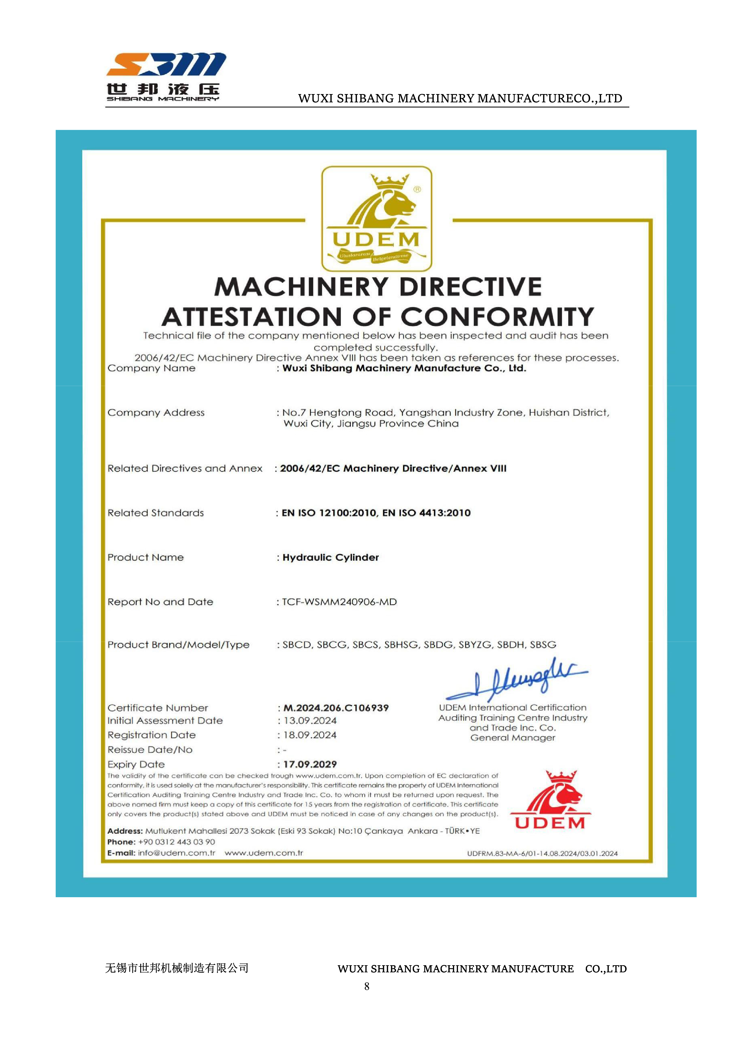
Compliance evidence is part of the mounting decision: the CE Machinery Directive attestation for hydraulic cylinders cites 2006/42/EC Annex VIII, EN ISO 12100:2010 and EN ISO 4413:2010.
Compliance is worth mentioning here because mounting choices feed directly into machine-level conformity. The manufacturer holds a CE Machinery Directive Attestation of Conformity for hydraulic cylinders, certificate M.2024.206.C106939, issued by UDEM International Certification Auditing Training Centre, valid to 17 September 2029, referencing 2006/42/EC Annex VIII, EN ISO 12100:2010 and EN ISO 4413:2010. It also holds ISO 9001, ISO 14001 and ISO 45001 certification, and CE Pressure Equipment certificates issued by TÜV SÜD Industrie Service GmbH under Directive 2014/68/EU Module G, with a stated scope of piston accumulator.
One further market signal belongs in an evaluation file. The U.S. Department of Commerce initiated antidumping and countervailing duty investigations of certain linear hydraulic cylinders and parts thereof in 2024. For buyers sourcing for North American frames, that is a commercial variable to track alongside the technical ones, because it can affect landed cost and delivery scheduling independent of cylinder quality.
What to expect next on frame interfaces
Two directions look likely to shape mounting selection over the next equipment cycles, and both are already visible in the SB-Y1 capability set rather than being speculative.
The first is instrumentation at the mounting point. Published customization scope for the line includes position measuring, proximity switches and control systems, and the Dammam project shows how tightly synchronized multi-point lifting depends on knowing where each cylinder actually is. As more heavy frames move to coordinated multi-cylinder motion, the mounting interface increasingly has to accommodate sensing and cabling, not just mechanical reaction.
The second is that mounting will keep being treated as a specification line rather than a default. The customization list already separates mounting from bore, stroke and pressure class, and the standards landscape — particularly ISO/TS 13725:2021 buckling-load evaluation for single and double acting cylinders — reinforces the idea that a cylinder's structural behaviour is a function of its end conditions. A buyer who specifies mounting explicitly is working with that logic rather than against it.
Frequently asked questions
Which SB-Y1 mounting configuration suits a pivoting heavy equipment frame?
The head trunnion and the base U-clevis are the configurations documented for pivoting and linkage duty. SB-Y1 documentation describes this family as designed for heavy-duty industrial applications requiring pivoting execution, with a structural configuration that supports linkage and continuous angular drive. Flange options belong to standardized linear applications instead.
Can a flange-mounted SB-Y1 cylinder be used where the load path changes angle during the stroke?
A flange is a clamped face and assumes the cylinder axis remains square to the mounting pad. Where the working member articulates, the angular change is transferred into the flange bolts and the barrel-to-flange junction as bending. For genuinely articulating duty, a pivoting configuration is the appropriate family rather than a flange.
What bore and stroke range is documented for SB-Y1 cylinders?
The documented supply record covers custom bore, rod and stroke combinations from 40/28/400 mm up to 320/220/2,900 mm, plus 100/70/4,630 mm long-stroke push-pull cylinders, across 34 cylinders delivered to two steel rolling mills. These are documented deliveries rather than a declared maximum range.
Does the mounting choice change the pressure the cylinder can be specified for?
The evidence set does not publish a per-configuration pressure matrix. It documents a 35 MPa heavy-duty hydraulic system in a four-point lifting project and separate bore, rod and stroke data in the rolling-mill supply, but not a combined rating for each mounting option. Pressure class is listed among customizable parameters and is confirmed at quotation against the specific configuration.
How is the mounting configuration confirmed before production?
Mounting is one of the customizable parameters alongside bore, rod diameter, stroke, pressure class, fluid and seals, piston-rod coating, cushioning, position measuring, proximity switches and control systems. The configuration is fixed through the quotation and project specification, and each cylinder is acceptance-tested before delivery under an ISO 9001 quality system.
Where can a buyer find the full configuration and capability record?
The manufacturer publishes an English-language product brochure covering the cylinder range and capability details, available for public download at the Wuxi Shibang hydraulic cylinder brochure.
Есть вопросы или нужны дополнительные детали?
Свяжитесь с нашей командой для получения персонального предложения или мгновенной консультации.
Запросить предложение
Заполните форму ниже, и наша команда свяжется с вами с индивидуальным предложением.
Прямой чат WhatsApp
Предпочитаете общаться в реальном времени? Напишите нам в WhatsApp для мгновенной помощи и быстрых ответов.
- Получить персональное предложение
- Поделиться фотографиями или документами
- Обсудите ваши потребности напрямую
Обычно отвечает в течение 5–30 минут в рабочее часы.