
RobotScan Series FAQ: Inline Acceptance Criteria and TCO
Automated inline dimensional inspection has moved past the pilot stage for small and medium machined parts. The decision that determines whether such a project succeeds, however, is rarely scan speed. It is whether buyer and supplier agreed in writing on how accuracy will be proven, how the software will connect to the quality system, and what the cell will cost to own across its service life.
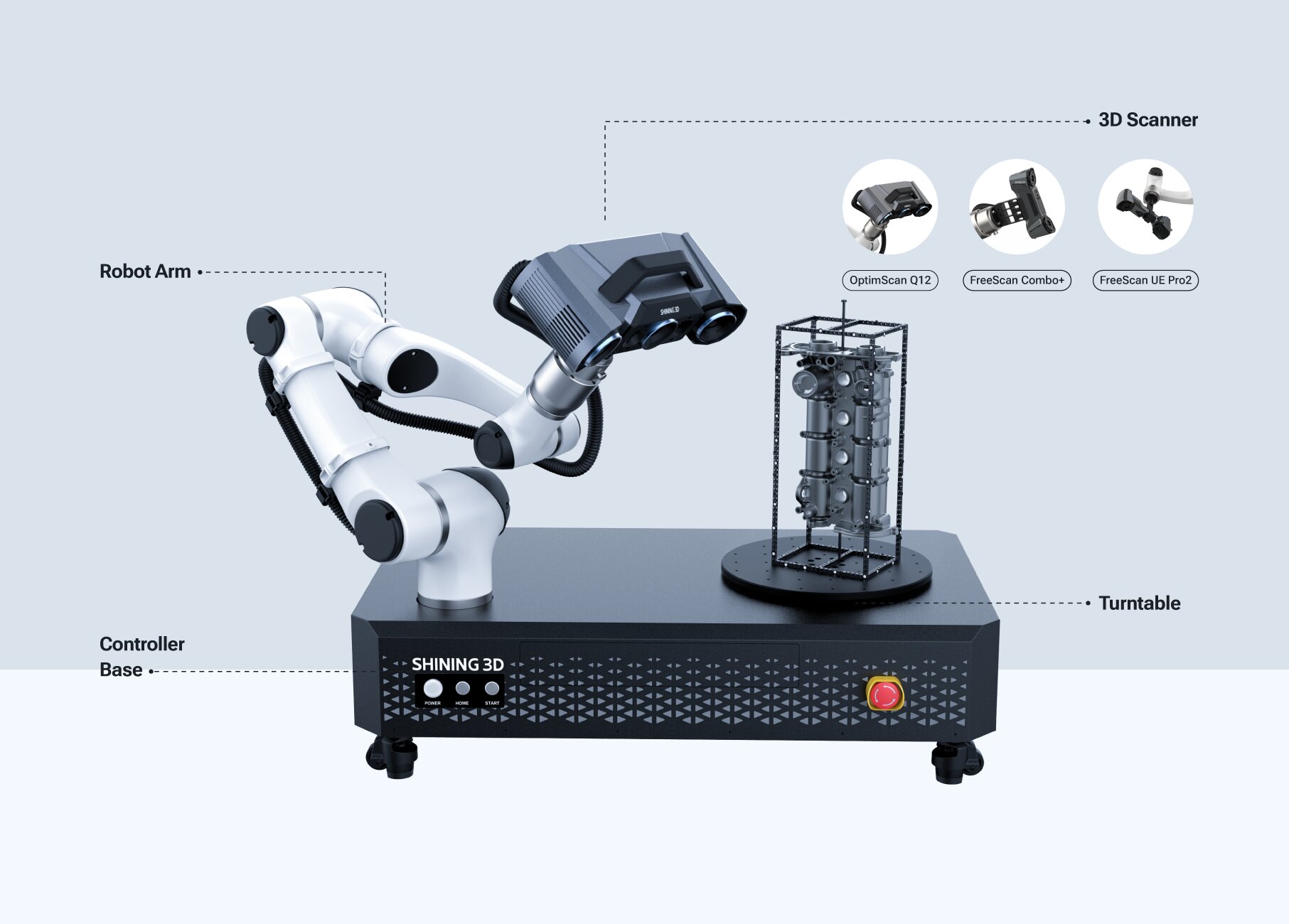
A 3D scanner on its own is a data capture device. A RobotScan cell is an inspection system: a metrology-grade 3D scanner mounted on an industrial or collaborative robot, paired with a turntable, fixtures, and control and inspection software. Each element changes the acceptance result differently, and each carries a different cost profile.
This FAQ is written for quality managers, manufacturing engineers and procurement teams in the research phase. It assumes the reader already accepts that full-field 3D data is useful, and now needs to know what to specify, what evidence to request, and what to model before committing to an inline deployment.
Why Inline 3D Inspection Projects Stall on Paper
A recurring failure mode appears before any hardware is installed. A supplier quotes an accuracy figure. The buyer writes that figure into the purchase order. Months later, at site acceptance, neither party can agree on whether the requirement has been met, because the figure never specified whether it referred to a single point or to the whole measurement volume, at what temperature, against which artefact, and re-verified by whom.
The scale of the category explains why this matters commercially. Grand View Research estimated the global 3D scanning market at USD 4.28 billion in 2024. Precedence Research reported that the quality control and inspection application segment held the largest share of that market in 2024, that structured light scanners dominated the product segment, and that short-range scanners of one metre or less accounted for the largest share by range. The centre of gravity of the market sits precisely where automated cells are most often deployed: small, high-precision parts inspected in volume.
That is the opportunity. An inline cell is justified when inspection volume is high enough to amortise the integration work, and when the quality cost of missed defects is measurable. Both conditions can be tested before purchase, but only if acceptance criteria are written as measurable clauses rather than as a single accuracy number.
What the RobotScan Series Includes
SHINING 3D is a high-precision 3D vision technology company founded in 2004 and headquartered in Hangzhou, China, with subsidiaries in Stuttgart, Barcelona, California, Florida and Tokyo. Its portfolio covers metrology 3D scanners, professional 3D scanners, entry-level 3D scanners and dental 3D solutions, with the EU, USA and APAC as major markets and exports accounting for approximately 70% of sales.
The RobotScan Series is the company's automated 3D measurement line. A configuration combines a high-accuracy 3D scanner, an industrial robot or collaborative robot, a turntable, fixtures, and control and inspection software. Three preconfigured variants address different part families, and the series can also be ordered as a fully customised configuration in which the robot brand, the SHINING 3D scanner model, the turntable, the fixtures and the control and inspection software are all specified to the application.
RobotScan Q12
RobotScan Q12 uses fringe projection, the optical method best suited to high accuracy and detailed data on small parts with complex surfaces, geometries or sharp edges. Typical workpieces include airfoils, brackets, connectors, gears, housings and electronic components. It is positioned as an automated optical 3D measurement solution with high repeatability and high efficiency for mass-production inspection.
RobotScan UE Pro2
RobotScan UE Pro2 uses handheld blue laser scanning, a method with strong adaptability to black, shiny and reflective surfaces. It suits small and medium sized sheet metal parts, casting housings, machining parts and mold components. Wireless and wired connectivity allow flexible on-site integration, and the configuration is positioned as an automation optical measurement solution balancing accuracy and efficiency.
RobotScan Combo+
RobotScan Combo+ uses a hybrid light source for versatility across part types. It targets efficient batch inspection of small to medium sized castings and machined parts, and mixed-size components such as covers, trim pieces, assemblies and medium castings. It is the cost-effective automated option for manufacturers with diverse inspection needs.
| Specification | RobotScan Series |
|---|---|
| Measurable object size | ≤ 500 mm |
| Turntable load capacity | ≤ 20 kg |
| Robot working radius | 800 mm |
| System weight | 70 kg |
| Configuration scope | Robot arm, SHINING 3D scanner, turntable, fixtures, control and inspection software |
How an Automated Cell Completes an Inspection Cycle
An automated optical inspection cycle follows the same stages as a manual 3D inspection workflow, with the first and last stages handled by the cell rather than by an operator.
- Data acquisition. The robot presents the scanner to the part along a taught path while the turntable indexes the workpiece. High-precision scanners capture complex geometries, freeform surfaces and detailed features that are difficult to reach with traditional methods.
- Data processing and alignment. Point cloud and mesh data are optimised, redundant information is removed, and the dataset is aligned to the reference frame before analysis.
- CAD comparison and deviation analysis. Scanned data is compared with the CAD reference, and colour deviation maps expose dimensional variation and manufacturing drift.
- Dimensional inspection and GD&T evaluation. Critical dimensions, geometric features and tolerance requirements are evaluated against engineering standards.
- Report generation. Measurement results, deviation information and analysis data are organised into traceable reports that support digital quality management.
- Batch repetition. Where a path and inspection template have been stored, repeated parts can be measured with minimal operator intervention, which is the point at which automation begins to pay back.
The difference between a working cell and a failed project usually lies in stages two to five, not in stage one. Capture is the visible part; alignment strategy, tolerance definition and report structure determine whether the output is usable as a quality record.
The Acceptance Criteria That Belong in the Contract
Acceptance criteria should be written as testable clauses. The ten items below cover the gaps that most often surface at site acceptance.
- Accuracy type and declaration. State whether the requirement refers to single-point accuracy, volumetric accuracy, or both, and over which measuring range.
- Acceptance test standard. Name the standard applied to the configuration, not to the product family in general.
- Calibration traceability. Require a certificate issued by an accredited laboratory, with the artefact identified and the re-verification interval defined.
- Repeatability. Specify how many repeated measurements of the same part are required, and how much spread is acceptable.
- Part coverage. Confirm that the test parts fall inside the specified envelope for object size, turntable load and robot reach.
- Cycle time definition. Separate loading, scanning, processing and reporting, so that a shortfall can be located rather than merely detected.
- Software and data flow. Identify which software performs the pass/fail judgement, which output formats are required, and how reports are archived.
- Installation conditions. Define foundation, guarding, temperature stability, vibration and lighting requirements, since optical measurement is sensitive to all of them.
- Golden sample and judgement rules. Agree the reference parts and the decision rules before the first measurement, not after a disputed result.
- Documentation and training. Include operating procedures, maintenance schedule, spare parts list and the response commitment for support.
Accuracy Evidence: What the Certificate Should Actually Say
Two standards families dominate optical 3D measurement acceptance. VDI/VDE 2634 Part 3 is the guideline for acceptance and reverification of optical 3D measuring systems based on multiple-view area scanning. The ISO 10360 series covers acceptance and reverification testing for coordinate measuring systems, and ISO 10360-12:2016 addresses articulated arm CMMs equipped with 3D scanners specifically.
The distinction matters when a robot-mounted scanner is being specified. A robot arm carrying an optical scanner is not the same architecture as an articulated arm CMM, and the applicable part of ISO 10360 depends on the system configuration. Buyers should ask the supplier to state which standard part was applied, to which configuration, and in which laboratory the test was performed.
Traceability depends on the laboratory. SHINING 3D operates an ISO/IEC 17025 accredited precision laboratory for dimensional calibration and inspection. The OptimScan Q12/Q9 fixed metrology scanners that can be integrated into a RobotScan configuration publish an acceptance test against VDI/VDE 2634 and ISO 10360, tested in that accredited laboratory, with accuracy of 0.015 mm in large range and up to 0.005 mm in small range. The OptimScan Q12/Q9 HD variant publishes 0.004 mm in small range and cites VDI/VDE 2634 Part 2 and ISO 10360. FreeScan handheld models used in other configurations publish 0.02 mm accuracy, tested to VDI/VDE 2634 Part 3 and ISO 10360.
A certificate is only useful if it matches the configuration being purchased. The document should name the scanner model, the measuring range, the accuracy value, the standard applied, the accredited laboratory, the date of test, and the calibration artefact used. A certificate issued for a different scanner model in the same family does not verify the installed system, and this is one of the most common documentation gaps found during supplier qualification.
Software Integration Is an Acceptance Item
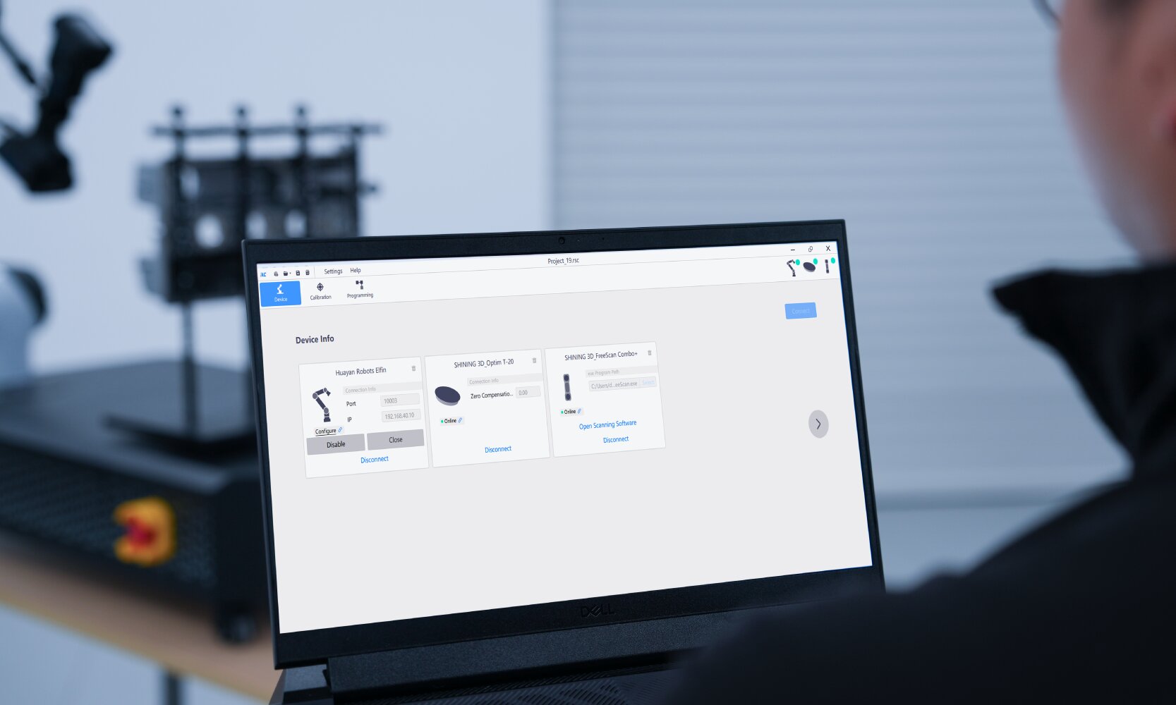
Inspection software determines whether captured data becomes a quality record. RobotScan configurations use RobotScan Control Software to manage robot motion, turntable indexing and the scan sequence, and pass data to an inspection module.
SHINING3D Inspect is a PTB-certified inspection module that provides compare, cross-section, feature, dimension, gauge, report and quick measurement functions. The cell can also output to third-party platforms including Polyworks, Geomagic Control X, EXModel Pro, Geomagic Design X and BlueStar Mapping. Scanner output formats across the relevant models include stl, obj, ply, asc, 3MF and P3.
Integration requirements should be settled before installation rather than negotiated afterwards. The practical questions are which software performs the pass/fail judgement, whether the inspection template has been validated, how reports are archived for traceability, and whether results must be pushed into a manufacturing execution or quality management system.
What Drives Total Cost of Ownership
Automated cells are frequently compared with standalone scanners on purchase price alone. That comparison misleads in both directions. A RobotScan configuration carries a higher initial cost than a handheld or desktop scanner because it includes a robot, a turntable, fixtures and integration services. Whether that premium is recovered depends on inspection volume, labour cost, and the cost of the defects the cell prevents.
| Cost category | What it includes | How it behaves |
|---|---|---|
| Initial equipment | Scanner, robot, turntable, fixtures, control and inspection software | Driven by configuration; robot brand and scanner model are the largest variables |
| Integration and commissioning | Path teaching, fixture design, line interface, trial production | Engineering effort; frequently underestimated in early budgets |
| Software | Inspection module, third-party licences, upgrades | Recurring or per-seat depending on the platform |
| Calibration and reverification | Artefacts, accredited laboratory time, production downtime | Recurring at a defined interval |
| Maintenance and spares | Robot servicing, optical components, wear parts | Scales with utilisation and duty cycle |
| Labour | Programming, template maintenance, report review | Relocated rather than removed by automation |
| Quality cost | Escapes, rework, scrap, containment | Directly influenced by accuracy and repeatability |
Three points are worth stating plainly. First, integration and fixture design are commonly underestimated; they are engineering projects, not installation tasks. Second, calibration and reverification are recurring costs, not one-off purchases, and they include production downtime. Third, automation does not remove labour; it relocates it from measurement to programming, template maintenance and report review.
The honest boundary is this: an automated cell is economically justified when inspection volume is high, part families are stable, and the quality cost of escapes is measurable. For low-volume, high-mix production, or for one-off inspection, a standalone metrology scanner is usually the better match.
Where the RobotScan Series Fits, and Where It Does Not
The series is specified for measurable object sizes up to 500 mm, turntable loads up to 20 kg, a robot working radius of 800 mm, and a system weight of 70 kg. Those figures define the production envelope as clearly as any accuracy claim.
Within that envelope, common applications include small complex parts such as airfoils, brackets, connectors, gears, housings and electronic components on the Q12 configuration; small and medium sheet metal parts, casting housings, machining parts and mold components on the UE Pro2; and small to medium castings, machined parts and mixed-size assemblies on the Combo+. Application industries listed for the series include automotive, energy and heavy industry, public utilities, engineering machinery and other transportation, marine, civil aviation, mold manufacturing and MRO.
Consumer electronics is a representative case. Housing and component inspection requires CAD comparison, dimensional deviation analysis, surface flatness checks, deformation and warpage analysis, and R-angle and cross-section measurement, with in-line automation inspection and no spray among the stated requirements. Automotive sheet metal, stamping die inspection, powertrain components and welding inspection follow similar logic, as does mold wear inspection, where scanner resolution sets the smallest detectable wear depth.
Outside the envelope, the series is not the right instrument. Parts larger than 500 mm, assemblies heavier than the turntable rating, or workpieces outside an 800 mm robot radius require a different configuration or a different product line entirely. Optical scanning also requires line of sight; deep cavities, undercuts and occluded features need additional viewing angles, complementary scanning modes or a different measurement method.
Comparison with Traditional Inspection Approaches
| Dimension | RobotScan automated cell | Standalone metrology 3D scanner | Contact CMM | Manual gauges |
|---|---|---|---|---|
| Data captured | Full-field surface geometry, automated and repeatable | Full-field surface geometry, operator-driven | Discrete points along a programmed path | Single features, as defined by the gauge |
| Operator dependency | Low during the cycle; higher during programming | High; results vary with operator technique | Medium; requires programmed routines and fixturing | High |
| Throughput on repeated parts | Suited to stable, high-volume part families | Suited to mixed or low-volume work | Slower per part; strong on defined feature sets | Fast per check, limited coverage |
| Complex and freeform surfaces | Strong; full-surface deviation maps | Strong | Limited by point density and probe access | Not applicable |
| Deep cavities and occlusion | Requires line of sight and additional viewing angles | Requires line of sight but easier to reposition | Advantageous; contact reaches where optics cannot | Depends on gauge geometry |
| Initial investment | Highest, including robot, turntable, fixtures and integration | Moderate | High, with environmental requirements | Lowest |
| Best fit | High-volume inspection of stable part families | Mixed-volume work, field use, first article inspection | Reference measurement, defined feature sets, regulated environments | Simple, high-volume shop-floor checks |
The comparison should not be read as a ranking. Contact CMMs remain a reference method for certain dimensional work, and manual gauges remain appropriate for simple, high-volume checks of a small number of features. The meaningful distinction is data coverage: optical scanning captures the full surface geometry in one measurement, which enables 100% surface inspection and detects shape deformations that key-point checks can miss. Against CMMs specifically, optical scanning is faster and returns richer data for complex and freeform surfaces.
The trade-offs run the other way too. An automated optical cell requires a stable installation, controlled lighting and a defined part presentation, and it depends on CAD models being available and correct. A CMM does not need line of sight and is less sensitive to surface finish. Buyers who need both contact and optical capability should plan for both rather than expect one system to replace the other.
What the Market Data Suggests
The demand pattern behind automated cells is measurable. MarketsandMarkets valued the global 3D metrology market, which includes 3D scanners for quality control, at USD 11.13 billion in 2024. Precedence Research reported North America at a 37% revenue share of the 3D scanner market in 2024, led by aerospace and automotive demand, while MarketsandMarkets projected Asia Pacific as the fastest-growing region for 3D metrology at an 8.0% CAGR through 2029. Grand View Research estimated the US 3D scanning market growing at over 7% CAGR from 2024 to 2030, driven by heavy machinery and defence.
Two structural trends support inline deployment. Mordor Intelligence reported that inline automated 3D inspection systems are increasingly replacing offline checks in the electronics sector to raise first-pass yields, and valued the 3D automated optical inspection equipment market at USD 2.74 billion in 2024 with a 7.32% CAGR. Precedence Research identified automotive as the largest end-user of 3D scanning technology for parts inspection and quality control.
The competitive landscape is concentrated at the top. SNS Insider identifies Hexagon, FARO and Carl Zeiss as Tier 1 global leaders in industrial metrology and 3D scanning. That matters for buyers in two ways: documentation and traceability expectations are set by that tier, and mid-tier suppliers are judged against it. SHINING 3D was recognised as an Emerging Leader in the global industrial metrology space by 360Quadrants in 2025, and reported 31% revenue growth in 2025 attributed to innovation in industrial metrology and global expansion.
Outlook
Three developments are likely to shape procurement decisions over the next planning cycle.
First, inspection is moving closer to the scan. SHINING 3D's FreeScan Omni series performs PTB-certified inspection on the device without a tethered computer, which indicates that the boundary between capture and analysis is dissolving. In an automated cell, the equivalent shift is a shorter path from scan to pass/fail decision, with fewer manual steps that can introduce variation.
Second, configurability is replacing fixed product tiers. Because the RobotScan Series can be assembled from different robot brands, scanner models, turntables, fixtures and software, the specification conversation is becoming an engineering conversation about part families rather than a catalogue selection.
Third, documentation is becoming a differentiator. Suppliers that maintain accredited laboratories, publish acceptance tests against recognised standards, and can trace a certificate to a specific configuration are easier to qualify in regulated supply chains. For buyers, the practical implication is that the accuracy certificate and the calibration record deserve as much evaluation attention as the scanner specification itself.
Frequently Asked Questions
What is the RobotScan Series?
The RobotScan Series is SHINING 3D's line of automated 3D measurement solutions. A configuration combines a high-accuracy 3D scanner, an industrial or collaborative robot, a turntable, fixtures, and control and inspection software. Three preconfigured variants are offered — RobotScan Q12, RobotScan UE Pro2 and RobotScan Combo+ — and the series can also be built as a fully customised configuration in which the robot brand, scanner model, turntable, fixtures and software are specified to the application.
Which parts can a RobotScan cell inspect?
The series is specified for measurable object sizes up to 500 mm, turntable loads up to 20 kg, and a robot working radius of 800 mm. RobotScan Q12 targets small parts with complex surfaces or sharp edges such as airfoils, brackets, connectors, gears, housings and electronic components. RobotScan UE Pro2 targets small and medium sheet metal parts, casting housings, machining parts and mold components. RobotScan Combo+ targets small to medium castings, machined parts and mixed-size assemblies such as covers, trim pieces and medium castings.
What accuracy can the RobotScan Series achieve?
Accuracy depends on the scanner integrated into the cell. Configurations using the OptimScan Q12/Q9 fixed metrology scanner publish 0.015 mm in large range and up to 0.005 mm in small range; the OptimScan Q12/Q9 HD variant publishes 0.004 mm in small range. Configurations using FreeScan handheld models publish 0.02 mm. Buyers should confirm the value for the exact scanner model and measuring range in their configuration, because values are not transferable across models within a family.
Which standards should the accuracy certificate reference?
VDI/VDE 2634 Part 3 is the guideline for acceptance and reverification of optical 3D measuring systems based on multiple-view area scanning. The ISO 10360 series covers acceptance and reverification for coordinate measuring systems, and ISO 10360-12:2016 addresses articulated arm CMMs equipped with 3D scanners. The applicable part depends on system architecture, so the certificate should state the standard applied, the configuration tested, the laboratory and the date.
How is a RobotScan cell verified before acceptance?
Verification combines document review and physical test. The document review confirms the calibration certificate, its traceability to an ISO/IEC 17025 accredited laboratory such as SHINING 3D's precision laboratory, and the standard applied. The physical test measures a known artefact and a set of production-representative parts, repeats the measurement to establish repeatability, and compares results against agreed acceptance values. Both stages should use the fixtures and software that will be used in production.
How does the system integrate with inspection software?
RobotScan Control Software manages robot motion, turntable indexing and the scan sequence. Data is passed to SHINING3D Inspect, a PTB-certified module providing compare, cross-section, feature, dimension, gauge, report and quick measurement functions, or to third-party platforms including Polyworks, Geomagic Control X, EXModel Pro, Geomagic Design X and BlueStar Mapping. Scanner output formats across the relevant models include stl, obj, ply, asc, 3MF and P3.
What are the operating limits of the RobotScan Series?
The specified envelope is measurable object size up to 500 mm, turntable load up to 20 kg, robot working radius of 800 mm, and system weight of 70 kg. Parts outside that envelope require a different configuration or a different product line. Optical scanning also requires line of sight, so deep cavities and occluded features need additional viewing angles or a complementary measurement method.
What drives total cost of ownership for an automated cell?
The main cost categories are initial equipment, integration and fixture design, software licensing and upgrades, calibration and reverification including downtime, maintenance and spare parts, operator and programmer time, and the quality cost of escapes. Initial equipment cost is higher than a standalone scanner because it includes the robot, turntable, fixtures and integration. Whether that premium is recovered depends on inspection volume, labour cost and the measurable cost of the defects the cell prevents.
How does automated optical inspection compare with CMM and manual gauging?
Optical scanning captures full-field surface geometry in one measurement, which enables 100% surface inspection and detects shape deformations that key-point checks can miss. Compared with CMMs, it is faster and returns richer data for complex and freeform surfaces. Contact CMMs remain a reference method for certain dimensional work and do not depend on line of sight, while manual gauges remain appropriate for simple checks of a small number of features.
What should a buyer confirm before signing off?
Confirm five things in writing: the accuracy value tied to a specific scanner model and measuring range; the standard and accredited laboratory behind the calibration certificate; the acceptance test procedure including artefact, sample parts, repeatability runs and pass/fail thresholds; the software that performs the judgement and how reports are archived; and the recurring calibration and maintenance obligations with their associated downtime. Each item should be testable at site acceptance rather than inferred from a datasheet.
Есть вопросы или нужны дополнительные детали?
Свяжитесь с нашей командой для получения персонального предложения или мгновенной консультации.
Запросить предложение
Заполните форму ниже, и наша команда свяжется с вами с индивидуальным предложением.
Прямой чат WhatsApp
Предпочитаете общаться в реальном времени? Напишите нам в WhatsApp для мгновенной помощи и быстрых ответов.
- Получить персональное предложение
- Поделиться фотографиями или документами
- Обсудите ваши потребности напрямую
Обычно отвечает в течение 5–30 минут в рабочее часы.