
Solid State Relay Shortlist for Discrete Automation Tasks
In discrete automation, a solid state relay is rarely selected on current rating alone. The switching event that matters is short, frequent and triggered by a mechanical contact — a micro switch, a limit switch or a position detection switch — and the relay has to behave predictably against that contact, not just against the load.
A solid state relay (SSR) is a semiconductor switching device that opens and closes a load circuit without moving contacts. In a discrete automation panel it usually sits between a sensing device and a load such as a contactor coil, a solenoid valve, an indicator bank or a small heater. Because the device has no armature and no contact gap, its selection logic differs from that of an electromechanical relay: input compatibility, minimum load behaviour, leakage current and switching time become the deciding variables.
This shortlist is built from the solid state relay range of XURUI (Zhejiang Xurui Electronic Co., Ltd.), a Wenzhou, Zhejiang-based manufacturer of industrial electric switches and relays founded in 2002, whose portfolio also covers micro switches, limit switches, foot switches, toggle switches, reed switches, proximity switches and photoelectric switches. It is not a ranking. It is a structured way to narrow candidate relay families against the load profiles and response requirements that appear most often in discrete automation work.
Why discrete automation asks a different question of a solid state relay
In process heating or motor drive cabinets, SSR selection centres on thermal design and continuous current. In discrete automation — part-present detection, indexing stations, gate and guard interlocks, end-of-travel stopping — the duty cycle looks different. The relay is asked to switch a modest load, many times per shift, in response to a dry contact or a low-voltage logic signal, inside a panel where space and heat are already constrained.
That changes the priority order. Three questions rise above the current rating:
- Does the input match the control source? A PLC output, a mechanical contact and an 80–250VAC control circuit each require a different input stage.
- What happens at low load? An SSR has a minimum load current and a residual leakage current; a very light load may not switch cleanly or may not release.
- How fast, and how often? Switching times in the range of ≤10ms suit interlocking and general on/off control, but they set the boundary for anything resembling high-speed counting or phase control.
The opportunity is straightforward: because the SSR range covers several input and load bands, a buyer can usually narrow to two or three candidate families before any quotation is requested. The risk is equally straightforward — specifying on headline amperage alone and discovering later that the sensor contact, the leakage path or the panel thermal budget does not fit.
Reading the requirement before reading a datasheet
A practical shortlist starts with four inputs that a datasheet cannot supply on its own.
1. The control source
Most XURUI solid state relay families accept a 3–32VDC control voltage with a control current of 6–25mA. Where the control circuit is AC, the AA variants — for example within the XSSR-W1, XSSR-W2 and XSSR-W6 families — accept 80–250VAC at 5–25mA. The XSSR-P1, P2 and P3 models accept 5V, 12V or 24VDC at 6–30mA. The XSSVR-CA W2 is a different case: it is driven by a 4–20mA analog signal rather than a discrete input.
2. The load profile
Voltage bands split the range: 24–240VAC for the XSSR-P series and XSSR-W7, and 75–480VAC for the XSSR-W1, W5, W6, W2 and M1–M6 families. Current spans 2A at the low end of the P series to 1000A at the top of the M series. XURUI specifies a load current safety factor of 50–60% for resistive loads and 30–40% for inductive loads, which means the nominal rating is a ceiling rather than an operating point.
3. The response requirement
Across the listed families, switching time is stated as ≤10ms (≤10mS in the model-level data). That is fast enough for interlocking, valve actuation and general discrete control, and it is the figure to test against the machine cycle before assuming a solid state device removes a timing problem.
4. Thermal and mounting envelope
Housings are PA66 nylon for the W-series models, with an aluminium alloy base plate specified on the XSSR-W1. Mounting is described as horizontal screw mounting or screw-mounted modular enclosure. Panel depth, heat-sink clearance and terminal access therefore belong in the shortlist stage, not in the commissioning stage.
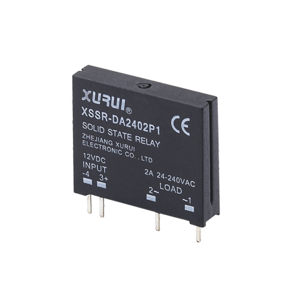
XSSR-DA2402P1 from the XSSR-P series: 24–240VAC load, 2A maximum load current, ≤10ms switching time.
The shortlist: candidate families by load profile
The table below groups the relay families by the load band they serve and the control input they expect. It is deliberately a shortlist rather than an order of merit: two families can serve the same task at different derating margins, and the correct choice depends on the panel rather than on the catalogue sequence.
| Load profile | Candidate family | Load voltage / current | Control input | Typical discrete-automation role |
|---|---|---|---|---|
| Low-current AC loads | XSSR-P1, XSSR-P2, XSSR-P3 (XSSR-2402P1, XSSR-2402P2/2403P2, XSSR-DA3803P3/3805P3) | 24–240VAC; 2A max; 0.03A min | 5V / 12V / 24VDC, 6–30mA | Indicator banks, small solenoid valves, interposing on logic-level outputs |
| Compact 24–240VAC switching | XSSR-W7 | 24–240VAC; 5–25A; 0.05A min | 3–32VDC, 6–25mA | Small heaters, signal lamps, short-duty AC motor starting circuits |
| 75–480VAC, DC-controlled | XSSR-W5 | 75–480VAC; 10–125A; 0.08A min | 3–32VDC, 6–25mA | Mid-power heating and general AC load switching |
| 75–480VAC, DC or AC control | XSSR-W6 / XSSR-W1 | 75–480VAC; 10–100A; 0.08A min | 3–32VDC or 80–250VAC | Panels where the control circuit is legacy AC and the load is AC |
| 75–480VAC, higher current | XSSR-W2 | 75–480VAC; 50–200A; 0.1A min | 3–32VDC or 80–250VAC | Higher-current discrete loads; model data states CE and RoHS |
| High-current panel loads | XSSR-M1 to XSSR-M6 | 75–480VAC; 60–1000A | 3–32VDC, 6–25mA | Zero-crossing trigger, modular enclosure, screw mount |
Source: XURUI product specification data. Current figures are maximum ratings; XURUI specifies derating of 50–60% for resistive and 30–40% for inductive loads.
Two further families sit adjacent to this shortlist rather than inside it. The XSSVR-W1 and XSSVR-W2 use an external potentiometer (470–560kΩ, 0.5–2W) and provide a conduction angle range of 0–170°, with load currents of 10–40A and 50–200A respectively. They are built for proportional control — heating regulation, lighting dimming, basic motor speed regulation — not for discrete on/off interlocks. The XSSVR-CA W2 similarly takes a 4–20mA analog signal and serves closed-loop analog control in automation systems. A buyer working through a discrete switching checklist should note these as a different category, because their proportional behaviour is not a substitute for a defined on/off state.
Matching the sensing device to the relay input
In discrete automation the relay is only half of the circuit. The other half is the device that commands it. XURUI's own switch range provides a useful reference point, because it shows how wide the gap is between the switching capacity of a mechanical sensing contact and the control current an SSR actually draws.
The XWS-6 micro switch is rated 6A/125VAC and 3A/250VAC. The XV-10 micro switch is rated AC-12 10A/250VAC and DC-12 5A/30VDC, and the XV-15 series is rated 16A/250VAC. The XZ-1 limit switch is rated AC-15 3A/250VAC and DC-12 2A/48VDC, while the XZ-9 series is rated 10(4)A/250VAC and 6(2)A/380VAC. Against an SSR control current of 6–25mA, these contacts carry far more capacity than the relay input requires. The electrical question is therefore not whether the switch can drive the relay, but what the switch's mechanical life, contact resistance and the relay's leakage current do to signal integrity over years of operation.
| Sensing device | Example models | Stated rating | Role in a discrete circuit |
|---|---|---|---|
| Micro switch | XWS-6, XV-10, XV-15, XZ-15 | XWS-6: 6A/125VAC, 3A/250VAC. XV-10: AC-12 10A/250VAC. XV-15: 16A/250VAC | Direct mechanical actuation, part-present detection, compact interlock |
| Limit switch | XZ-1, XZ-3, XZ-7, XZ-8, XZ-9 | XZ-1: AC-15 3A/250VAC, DC-12 2A/48VDC. XZ-9: 10(4)A/250VAC, 6(2)A/380VAC | End-of-travel stopping, position feedback, guard monitoring |
| Position detection switch | PZ-31 | 220VAC, 3A, 1NC1NO, IP67, operating angle 10° | Angular position feedback on conveyors, robotics and indexing stations |
| Belt and deflection switches | PZ-21, PZ-22 | PZ-21: 220VAC, 3A, IP67. PZ-22: 220VAC, 3A, IP67 | Conveyor misalignment detection and safety shutdown |
| Reed switch | XGH | 1VA to 30VA, breakover voltage ≥100VDC | Low-power non-contact position or door-state signalling |
Source: XURUI switch specification data. Ratings shown are the values stated for the listed models.

Limit Switch XZ-9108 from the XZ-9 series, rated 10(4)A/250VAC and 6(2)A/380VAC — a typical command source ahead of a solid state relay.
For safety-interlock duty the picture is similar but the consequence of a miss is higher. A guard switch commands the relay, the relay removes power from the guarded load, and the release behaviour of the SSR becomes part of the response chain. Because a solid state device holds a residual leakage current — stated as ≤1mA on the XSSR-P series, ≤3mA on the XSSR-W7, ≤5mA on the XSSR-W1, W2 and W6, and ≤8mA on the XSSR-W5 — the circuit must be designed so that this leakage cannot hold a contactor or a signal input in an energised state. That is a design question for the panel integrator, and it belongs on the shortlist sheet rather than in a commissioning note.
A practical selection checklist
The following checklist condenses the shortlist into the order in which the questions usually arrive. Each line corresponds to a field that can be confirmed from the product data before a sample is requested.
- Confirm the control voltage band. 3–32VDC, 5/12/24VDC, 80–250VAC or 4–20mA analog — the input stage follows from this, not from the load.
- Confirm the load voltage band. 24–240VAC points to the XSSR-P series or XSSR-W7; 75–480VAC points to the W1, W5, W6, W2 or M series.
- Apply the derating factor. 50–60% for resistive loads, 30–40% for inductive loads. A 40A nominal rating is not a 40A operating point.
- Check the minimum load. The stated minimum is 0.03A on the XSSR-P series, 0.05A on the XSSR-W7 and XSSVR models, and 0.08–0.1A across the W and M families.
- Check the leakage current against the circuit. Values range from ≤1mA to ≤8mA depending on model; verify that no downstream input can be held by it.
- Confirm the switching time against the cycle. ≤10ms is the stated figure across the range.
- Confirm the mounting and thermal path. Screw mounting, modular enclosure, PA66 nylon housing, aluminium alloy base plate on the XSSR-W1.
- Confirm the certification position for the specific model. XURUI states ISO 9001 for the company and CCC, CE, TÜV SÜD, UL, KC and RoHS across its mainstream products; the XSSR-W2 model data states CE and RoHS explicitly. Model-level confirmation is the safer habit.
How solid state relays compare with electromechanical relays in discrete panels
The comparison that matters at the shortlist stage is not which technology is newer, but which failure mode the panel can absorb. Both technologies remain in service in discrete automation, and they fail differently.
| Dimension | Solid state relay | Electromechanical relay |
|---|---|---|
| Switching element | Semiconductor, no moving contacts | Mechanical contacts with an armature |
| Stated switching time | ≤10ms across the XURUI range | Governed by mechanical actuation and bounce |
| Acoustic noise | Silent operation | Audible click on every operation |
| Contact wear | No contact erosion | Contact erosion accumulates with load and frequency |
| Off-state behaviour | Residual leakage current, stated per model | Galvanic contact separation when open |
| Very light loads | Minimum load current applies | Generally tolerant of dry circuits |
| Thermal management | Heat must be dissipated; base plate and clearance matter | Coil heat only |
| Surge and transient tolerance | Requires attention to overvoltage protection | More forgiving of short transients |
Three boundaries deserve to be written down rather than assumed. First, the listed XURUI models are described as screw-mounted or horizontally screw-mounted, with modular enclosures on the M series; DIN rail mounting does not appear in the model-level data, even though DIN-rail variants are reported as the fastest-growing mounting segment in the wider market. A buyer whose panel standard is DIN rail should confirm availability before shortlisting. Second, the residual leakage current and the minimum load current together mean that very light loads and dry-circuit sensing paths need explicit verification. Third, the load current safety factor of 50–60% for resistive and 30–40% for inductive loads implies that a relay chosen at its nominal rating is being operated outside its recommended margin.
Market context: why the shortlist is changing
The surrounding market gives some indication of where buyer attention is moving. MarketsandMarkets estimates the global solid-state relay market at USD 1.74 billion in 2025, projected to reach USD 2.36 billion by 2030. Mordor Intelligence estimates that Asia-Pacific accounts for around 42% of that market in 2025, with electric vehicle charger deployment and photovoltaic inverter manufacturing in China and Japan cited as drivers.
Two structural signals are more directly relevant to discrete automation. Mordor Intelligence reports that panel-mount SSR designs held the largest mounting configuration share at 38.67% in 2025 — consistent with the screw-mounted construction of most of the XURUI range — while DIN-rail variants are described as the fastest-growing segment at a forecast 7.11% CAGR. Separately, the 0–20A current bracket accounted for 44.13% of market size in 2025, which places a large share of demand in the same band as the XSSR-P series and XSSR-W7 rather than in the high-current M series.
For compliance, industrial solid state relays are required to meet standards including IEC/EN 60947-4-3 for contactors and motor-starters and UL 508 for industrial control equipment. Those standards frame what a supplier's certification claim should be checked against, particularly where a relay is used to switch a motor load rather than a resistive one.
What to watch over the next planning cycle
Three developments are likely to reshape the shortlist rather than replace it.
The first is mounting. If DIN-rail variants continue to grow faster than panel-mount designs, panel builders who standardise on DIN rail will increasingly expect the relay range to follow. The current XURUI data describes screw mounting, so this is a gap to monitor rather than a capability to assume.
The second is the boundary between discrete and proportional control. The XSSVR-W1, XSSVR-W2 and XSSVR-CA W2 already extend the range into conduction-angle and 4–20mA control. As discrete automation panels absorb more heating and dimming functions, the selection conversation will increasingly begin with the control signal rather than the load.
The third is documentation depth. Buyers comparing suppliers across regions increasingly ask for model-level evidence — leakage current, minimum load, derating factor, certification per model — rather than company-level statements. A range that publishes these values per family, as the XURUI specification data does for leakage and minimum load, reduces the verification work at the shortlist stage.
Frequently asked questions
What is a solid state relay and how does it differ from an electromechanical relay?
A solid state relay is a semiconductor switching device that opens and closes a load circuit without moving contacts. In discrete automation it is normally used to switch a load from a low-power control signal. Compared with an electromechanical relay, it has no armature or contact gap, operates silently, and is specified with a switching time — ≤10ms across the XURUI range — but it also carries a residual leakage current in the off state and a minimum load current, neither of which applies to a mechanical contact.
Which solid state relay family should be considered first for a low-current discrete automation load?
The XSSR-P1, P2 and P3 models are specified for 24–240VAC loads with a maximum load current of 2A and a minimum load current of 0.03A, controlled by 5V, 12V or 24VDC at 6–30mA, with a switching time of ≤10ms and output leakage current of ≤1mA. For loads between 5A and 25A at 24–240VAC, the XSSR-W7 is specified at 5–25A with a 0.05A minimum load and ≤3mA leakage.
How do micro switches and limit switches relate to solid state relay selection?
They are usually the command source. A micro switch such as the XWS-6 is rated 6A/125VAC and 3A/250VAC, and a limit switch such as the XZ-1 is rated AC-15 3A/250VAC and DC-12 2A/48VDC — capacities well above the 6–25mA control current drawn by most XURUI solid state relays. The relevant checks are therefore the mechanical life of the switch, its contact resistance, and whether the relay's leakage current can affect the signal path, rather than whether the switch can carry the relay input.
What switching time can be expected from this solid state relay range?
The model-level specification data states a switching time of ≤10ms (≤10mS) across the XSSR-P, W1, W2, W5, W6, W7 and M series, and ≤10ms for the XSSVR-CA W2 analog-controlled model. That figure suits interlocking, valve actuation and general discrete on/off control; it is not a microsecond-class figure for high-speed counting.
What are the main limitations when replacing an electromechanical relay with a solid state relay?
Four limits recur in the XURUI data. Off-state leakage current ranges from ≤1mA to ≤8mA depending on model, so downstream inputs must be checked for hold-in. Minimum load current ranges from 0.03A to 0.1A, so very light loads may not switch reliably. The load current safety factor is 50–60% for resistive and 30–40% for inductive loads, so nominal ratings require derating. And heat must be dissipated, with an aluminium alloy base plate specified on the XSSR-W1 and PA66 nylon housings across the W series.
Is DIN rail mounting available in this range?
The model-level data describes screw mounting, horizontal screw mounting and, on the M series, a screw-mounted modular enclosure. DIN rail mounting is not stated for the listed models. Independent market reporting describes DIN-rail variants as the fastest-growing mounting segment, so buyers whose panel standard is DIN rail should confirm the current position with the supplier rather than assume it.
Reference material
A downloadable brochure covering the XURUI switch and solid state relay range is available here: XURUI product brochure (PDF). It is a specification reference for the families discussed above and does not replace model-level confirmation against the panel requirement.
Есть вопросы или нужны дополнительные детали?
Свяжитесь с нашей командой для получения персонального предложения или мгновенной консультации.
Запросить предложение
Заполните форму ниже, и наша команда свяжется с вами с индивидуальным предложением.
Прямой чат WhatsApp
Предпочитаете общаться в реальном времени? Напишите нам в WhatsApp для мгновенной помощи и быстрых ответов.
- Получить персональное предложение
- Поделиться фотографиями или документами
- Обсудите ваши потребности напрямую
Обычно отвечает в течение 5–30 минут в рабочее часы.