
Tap Changer Options for ANSI Substation Transformers, Ranked by Fit
Tap Changer Options for ANSI Substation Transformers, Ranked by Fit
Power Transformers · North America · Voltage Regulation
On North American substation projects the tap changer is usually the last item confirmed on the specification sheet, and the first component questioned at commissioning. That choice decides how a transformer holds secondary voltage across the daily load curve, how much maintenance the asset accumulates over a design life measured in decades, and how cleanly a new unit parallels with banks already in service. Under ANSI/IEEE-based procurement, tap range, step size and control philosophy are engineering decisions, not checkboxes copied from a previous project.
This reference covers the vocabulary buyers need before comparing options, four configuration families that account for most shortlists, the workflow that fixes a tap range, and the boundaries where a tap changer stops helping. Capability and project facts come from Winley Electric; market, price and regulatory figures come from published sources cited inline.
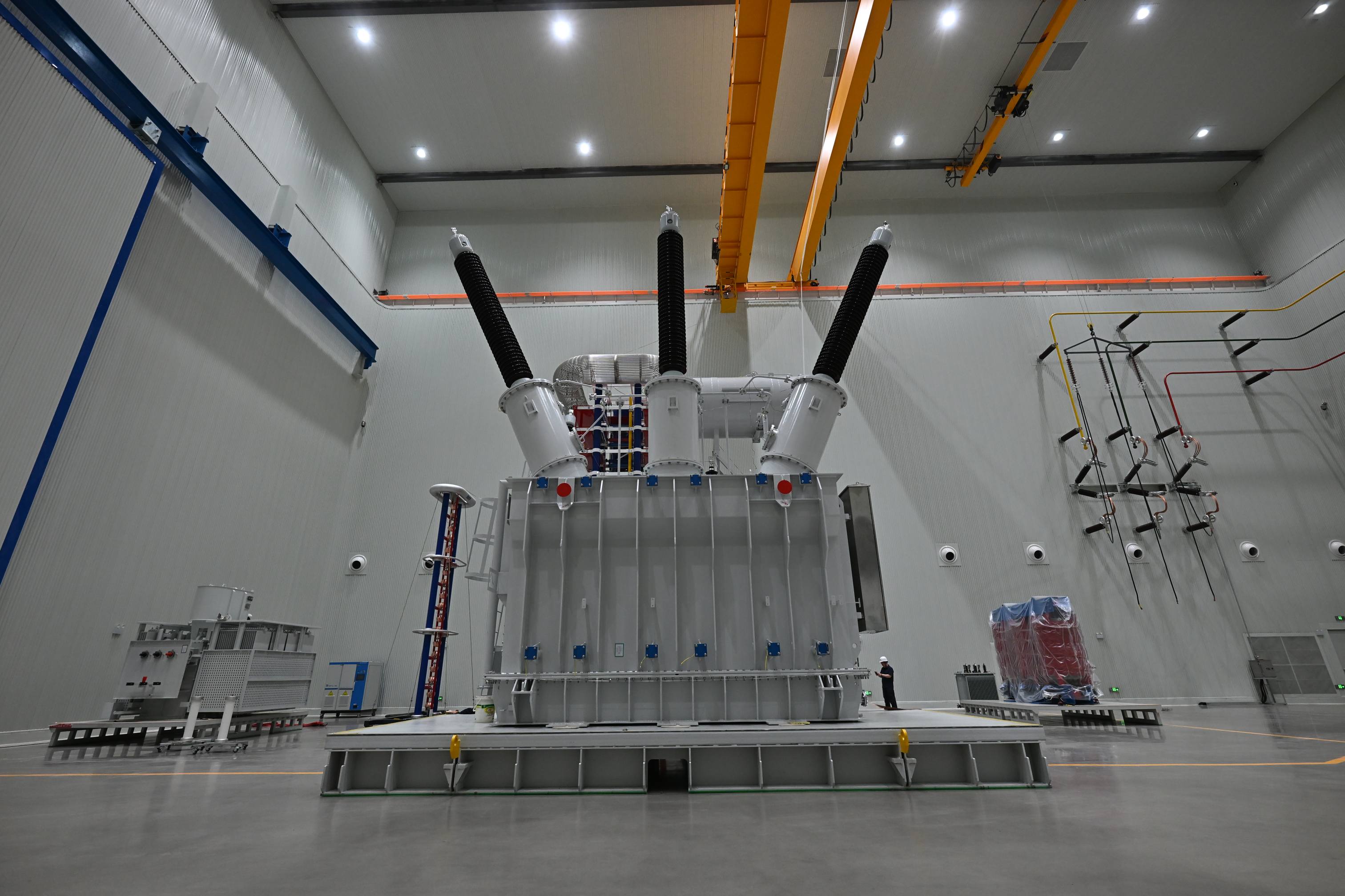
230kV 100/133/167MVA oil-immersed power transformer for grid substations — a capacity class where tap range and regulation conditions are fixed during specification.
Why tapping has become a procurement decision, not a detail
Two market signals explain why voltage regulation moved from the engineering appendix into the commercial discussion. Average lead times for power transformers in the United States reached 128 weeks as of Q2 2025, according to Mark & Spark Solutions. Over a similar window, the U.S. Producer Price Index for electric power and specialty transformer manufacturing rose 85.8% between 2019 and 2026, according to the U.S. Bureau of Labor Statistics.
Long reservation windows and higher unit prices change the cost of being wrong. When a unit is ordered well before energization, the voltage study that fixes the tap range is often finished before final load data exists. A tap winding change after award is not a paperwork correction: it reaches into the core-and-coil design, the test program and the delivery slot the project is already counting on.
Regulation also sits closer to efficiency than it used to. The DOE 2024 final rule for distribution transformers, 10 CFR 431.192, requires compliance by April 23, 2029 and encourages the use of both grain-oriented and amorphous steel. For buyers, the practical consequence is that loss evaluation and tap position are discussed in the same meeting: the losses a unit produces depend on where it operates on the tap range, so the assumptions behind a loss number belong in the specification, not in a footnote.
The vocabulary that makes comparison possible
Turns ratio and tap voltage. A tap changer regulates secondary voltage by changing the effective number of turns in the tapped winding. Each tap position corresponds to a defined ratio, and therefore to a defined secondary voltage at a given primary voltage. Nothing about a tap changer creates new capacity; it redistributes voltage accuracy.
Tap range, step size and step count. The tap range is the total band around nominal voltage that the tap winding can reach, normally expressed together with the number of steps and the size of each step. Range decides which system voltage conditions are covered; step size decides how closely the secondary voltage can be held inside that band.
Off-circuit tap changer (de-energized). Position changes are made with the unit de-energized, usually at commissioning or during planned outages. It is a set-and-forget device with no ongoing control loop and no wear from operating under load.
On-load tap changer (OLTC). Position changes are made while the transformer is energized and carrying load, driven by a motor drive and managed by a controller. On-load tap changers are wear items with a documented maintenance regime tied to operation counts, which is why the component brand and its spares pathway matter as much as the tap range.
Automatic voltage regulation (AVR). The controller compares measured secondary voltage against a setpoint and issues raise or lower commands within a deadband and time delay. Setpoint, deadband, delay and the parallel-operation strategy are project decisions, not factory defaults.
Parallel operation. Two transformers in parallel with mismatched tap positions circulate current between them. Master-follower or negative-reactance schemes exist to prevent that, and they only work if both units share compatible tap ranges, step sizes and control interfaces.
Verification. Routine testing confirms that the tap winding behaves as designed: turns ratio measured at each tap position, winding resistance, polarity and phase relation, and no-load loss. These are the tests that reveal a tap-range or connection error before the unit leaves the factory.
The IEEE C57 family sets the general requirements, rating conventions and test procedures that North American utilities and EPC contractors apply to substation power transformers; CSA requirements govern Canadian projects and IEC 60076 covers international work. Winley Electric engineers work to ANSI, IEEE, CSA, DOE 2016, NEMA and IEC conventions when a tap specification is developed.
Four voltage-regulation configurations, ranked by fit
The ranking below orders configuration families by how often they fit typical North American project conditions, and by how much engineering effort each one demands. It is a ranking of configurations, not of manufacturers. Comparison metrics are regulation frequency, maintenance burden, control complexity and the main cost driver.
| Rank | Configuration | Fits best when | What to watch |
|---|---|---|---|
| 1 | On-load tap changer with automatic AVR control | Utility step-down where load swings daily, where several banks operate in parallel, or where regional load growth keeps shifting the voltage profile | Maintenance tied to operation counts, control and SCADA integration, cabinet space |
| 2 | Off-circuit tap changer, position set at commissioning | Inverter-based generation and storage where the plant controller already handles continuous voltage and reactive power | No correction under load; seasonal changes need an outage |
| 3 | Wide-window taps with multiple secondary windings | Industrial substations feeding several medium-voltage buses from one platform | A single tap position is a compromise across buses with different drops |
| 4 | Three-winding designs with coordinated tap positions | High-voltage substations where one tap setting must serve a distribution level and a tertiary level at once | Coordination effort; tertiary voltage drifts when loading is uneven |
Rank 1 — OLTC with automatic regulation
This is the default choice for utility step-down duty, where the load curve is not under the operator's control. The value of an OLTC is not the tap range itself but the closed loop: the controller holds secondary voltage inside a deadband while upstream voltage and downstream load both move. Its cost is a moving component with a maintenance schedule and a control system that must be commissioned and integrated.
Rank 2 — Off-circuit tap changer on a renewable or storage project
Where an inverter-based plant provides continuous voltage and reactive power control, the substation transformer often needs the correct ratio rather than a dynamic one. An off-circuit tap changer set during commissioning is simpler, has no operating wear, and removes a control loop from the commissioning scope. It is the right answer only when the plant controls really are capable of holding the voltage band across the year.
Rank 3 — Wide-window taps with multiple secondary windings
Industrial substations that distribute from two medium-voltage levels gain more from a well-chosen fixed tap window than from dynamic regulation. A single platform feeding several medium-voltage buses with different cable drops will always be a compromise; the design question is which bus can tolerate the deviation.
Rank 4 — Coordinated taps on a three-winding transformer
In a three-winding unit, one tap position serves two secondary systems. The engineering effort is real, and it belongs in the specification before the winding layout freezes, because relocating or re-ranging a tapped winding later is a design change rather than a setting change.
Where Winley Electric fits into a tap-range decision
Xiamen Winley Electric Co., Ltd (Winley Electric) is a transformer manufacturer founded in 2014 and headquartered in Xiamen, China, with manufacturing facilities in Shanghai and Guangdong. The company produces oil-immersed and dry-type transformers with manufacturing capability up to 450 MVA and 230 kV, and exports to more than 60 countries, with a focus on North and South America.
Tap-changing systems sit inside Winley Electric's OEM and ODM customization scope for substation power transformers rated up to 450 MVA and 230 kV. That scope covers capacity, voltage ratio, winding configuration, impedance, loss levels, cooling method, tap-changing system, terminal arrangement, protection and monitoring functions, structural design, testing, documentation and transportation requirements. Customer-specified components from recognized brands such as Qualitrol, Eaton Cooper Power series and Maschinenfabrik Reinhausen (MR) can be integrated to match project standards and maintenance preferences.
Because the OLTC is a specified component rather than a generic fitment, the brand choice also fixes the spares pathway and the maintenance instructions that will follow the asset for its service life. Buyers evaluating a supplier should therefore ask not only what tap range is offered, but which component brands the supplier can integrate, and whether that integration is engineered to ANSI/IEEE, CSA or IEC requirements as the project demands.
Supporting capability behind a tap specification includes 35 engineers familiar with ANSI, IEEE, CSA, DOE 2016, NEMA and IEC conventions, ISO 9001 process management with dedicated QC oversight, and routine testing on every unit that includes winding resistance, turns ratio, polarity and phase relation, and no-load loss. The company also operates professional type-test equipment such as lightning impulse test devices. Winley Electric holds UL and cUL certification and can open UL partner authorization according to project needs, alongside ISO 9001, ISO 14001, ISO 45001, CE and TUV certifications. Delivery is quoted at 8–10 weeks for transformers below 10 MVA, 10–12 weeks for 10–40 MVA, 18–20 weeks for 40–100 MVA, and 20 weeks for 230 kV power transformers up to 450 MVA, with a minimum order quantity of one unit and a 24-month warranty from bill of lading.
A specification workflow for tap range and regulation conditions
- Fix the voltage band first. Establish the range of system voltage the transformer will actually see at the point of interconnection, including the existing bus records where a replacement unit will parallel with operating banks.
- Decide whether regulation must be dynamic. If the plant or the upstream system already controls voltage continuously, an off-circuit tap changer is a legitimate answer. If not, the OLTC carries the duty.
- Choose where the tap winding sits. Taps on the high-voltage winding and taps on the low-voltage winding produce different insulation and current consequences; the choice follows the ratio band and the current at each tap.
- Size the range against worst-case conditions, not average ones. A range that covers normal operation but not the extreme condition has not solved the problem. Oversizing the range adds cost and swings impedance across positions.
- Set the step count and step size together. Step size determines voltage resolution; step count determines whether the whole band is available. Both belong in the data sheet.
- Define the control philosophy in writing. Setpoint, deadband, time delay, parallel-operation scheme, remote interface and alarm mapping are project decisions that must be documented before the control cabinet is built.
- State the operating conditions used for loss and temperature evaluation. Losses and impedance shift with tap position; a loss figure without a stated tap condition is not comparable between bids.
- Confirm the verification plan. Turns ratio at every tap, winding resistance, polarity and phase relation and no-load loss should appear in the test schedule, together with any project-specific type tests.
Application evidence from North American projects
Regulation decisions become concrete when they meet a real schedule and a real voltage level. Winley Electric's North American project record spans several of the cases where tap and ratio decisions carry the most weight.
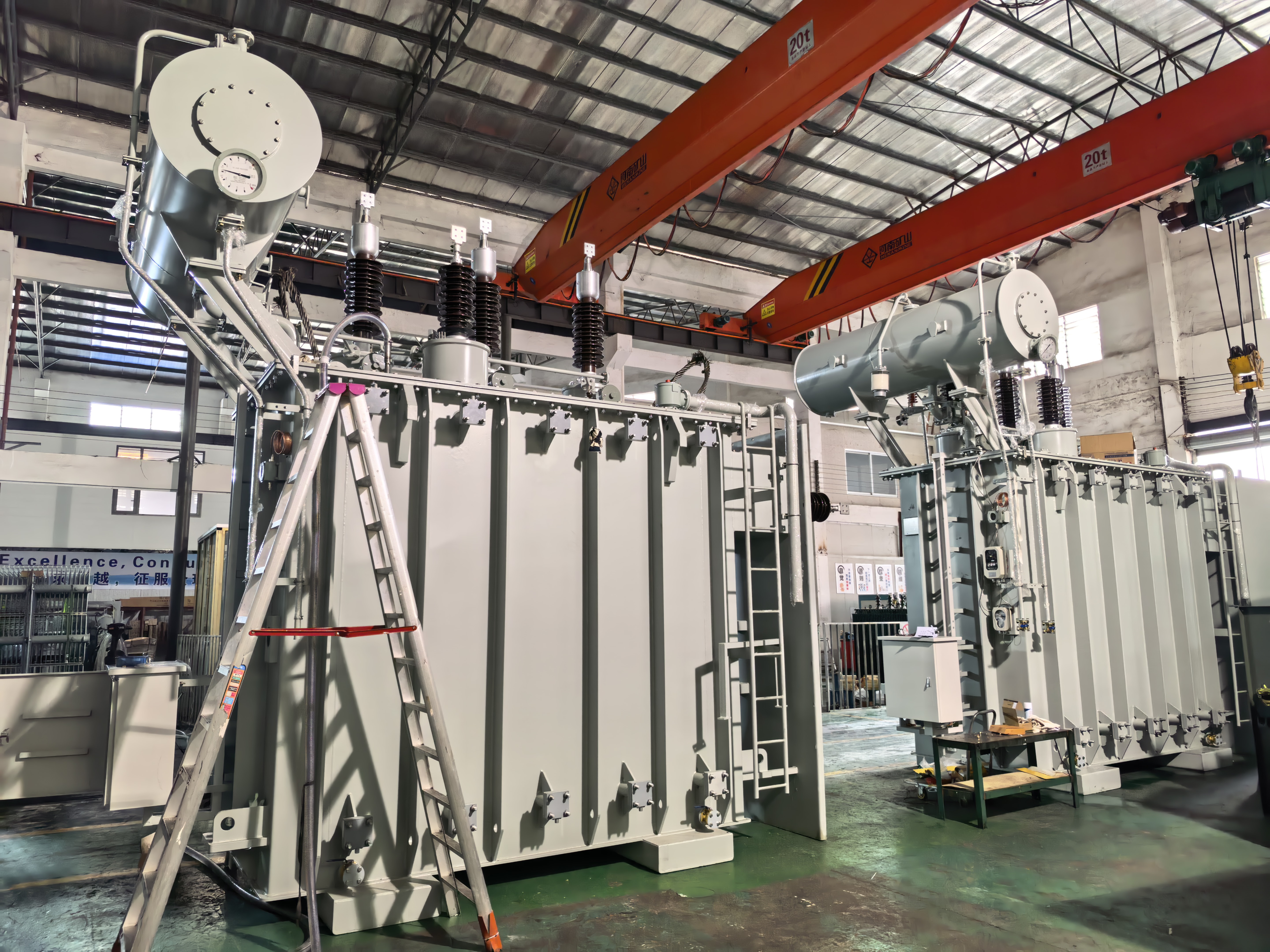
40MVA oil-immersed step-down substation power transformer, 44kV to 34.5kV, built to ANSI/IEEE requirements — a duty profile where the tap range is set by the distribution bus band.
For a U.S. utility, Winley Electric delivered two 40 MVA conservator-type liquid-filled step-down substation power transformers, with the full in-house production and testing cycle completed in 12 weeks, built to ANSI/IEEE requirements. In another U.S. utility project, the unit supplied was a 230/34.5/13.8kV three-winding transformer rated 100/133/167MVA, using a staged cooling design across the 100/133/167MVA range with integrated temperature and pressure monitoring, for high-voltage transformation in utility substations, regional grid expansion and large industrial power systems.
Industrial duty brings a different regulation question. For a U.S. EPC client, two custom 10–14 MVA substation transformers were manufactured within a 9-week production cycle in a Dd0y1y1 winding configuration, with multiple 2.4 kV and 4.16 kV secondary outputs so that one platform could serve several medium-voltage distribution buses. For an electrical contractor serving an industrial park and data center, two 34 MVA substation power transformers were built to ANSI/IEEE standards with 304 stainless steel construction and a NEMA 4X weatherproof enclosure, completed in 12 weeks.
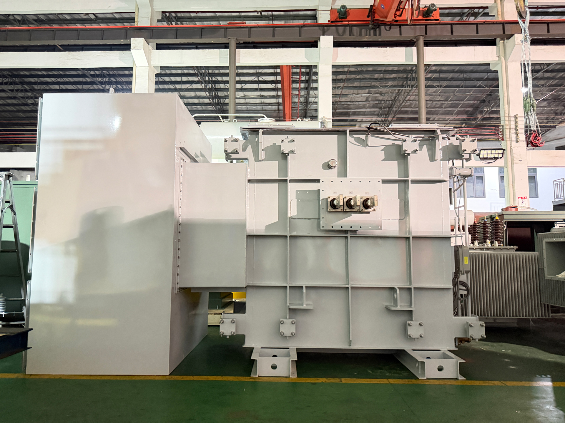
8MVA substation power transformer of the type used in a U.S. renewable project with dual LV split winding architecture and a stable 34.5kV output.
On the generation side, a U.S. renewable energy developer used a single 8 MVA unit across a utility-scale solar farm and co-located battery energy storage application, featuring dual LV split winding architecture, high thermal margin insulation, harmonic load resistance and IEEE C57 compliance, delivered in 90 days with a stable 34.5kV output. In a separate high-capacity case, a 230kV 225MVA three-winding power transformer was built to connect a 69kV energy storage substation system to the 230kV transmission grid, supporting bidirectional power transfer during charging and discharging.
The common thread is that the ratio and tap decisions were settled during specification, alongside winding configuration, impedance, cooling and protection and monitoring functions — all of which sit within the same customization scope as the tap-changing system.
What the 2026 market data implies for tap specification
The global transformer market is estimated to reach USD 88.48 billion by 2030, according to MarketsandMarkets. Growth of that scale is not absorbed evenly: it arrives as concentrated demand for high-voltage units, in a supply chain where U.S. lead times already averaged 128 weeks in Q2 2025 and the producer price index for electric power and specialty transformer manufacturing rose 85.8% between 2019 and 2026.
Three procurement behaviours follow from that combination. First, specification quality front-loads: the earlier a tap range is fixed, the less exposure a project carries to a design change during a booked production slot. Second, parallel-operation compatibility becomes a purchasing criterion rather than an afterthought, because new units increasingly join banks that are already in service. Third, regulatory timing enters the brief — the DOE 2024 rule under 10 CFR 431.192, with compliance required by April 23, 2029, keeps efficiency evaluation on the agenda for distribution-class equipment, and efficiency conversations inevitably reach the question of which tap position the loss figures were calculated at.
Where a tap changer stops helping
Traditional practice on many North American substations was a fixed ratio with a generous impedance margin and a link-board tap adjusted once at commissioning. That approach remains correct for stable, well-characterised loads, and it remains cheaper. The comparison is not between good and bad practice; it is between two levels of control effort.
| Dimension | Fixed ratio, commissioning tap only | Specified tap range with regulation |
|---|---|---|
| Voltage correction under load | None between outages | Continuous within deadband |
| Maintenance profile | No operating wear | Wear item with a scheduled regime |
| Engineering scope | Ratio and impedance only | Ratio, control, SCADA, parallel operation |
| Cost driver | Core, coil, tank | Component, cabinet, control and commissioning |
The limits deserve to be stated plainly, because they shape supplier evaluation more than any advantage claim:
- A tap changer corrects sustained voltage offset, not power quality. Fast flicker, harmonic distortion and load imbalance are not solved by changing tap position; those need other devices and other specifications.
- An OLTC is a wear component. Its operation count drives maintenance, and the component brand determines spares availability and service documentation for the life of the asset. A tap specification that names no component brand has left that open.
- An off-circuit tap changer cannot help during operation. If the voltage band moves seasonally, position changes require an outage, and the design should acknowledge that constraint rather than assume regular intervention.
- A wider tap range is not automatically better. Range interacts with impedance and losses across positions, and every added step is engineering and cost. A range sized to cover conditions the site will never see is over-specification.
- Regulation cannot compensate for an undersized unit. If capacity or thermal margin is inadequate, tap position shifts the problem rather than solving it.
- The boundary between manufacturer and component supplier is real. Winley Electric engineers and integrates the tap-changing system into the transformer and tests the tap winding; the OLTC component itself carries its own manufacturer's documentation and service requirements, which the buyer should obtain with the unit.
Future outlook
Three directions look durable for the next specification cycles. Regulation is moving toward monitoring: temperature, pressure and protection data are increasingly integrated rather than bolted on, which makes the control interface part of the initial scope. Bidirectional duty is becoming normal rather than exceptional, since storage projects require a tap and ratio strategy that works during both charging and discharging. And schedule pressure is unlikely to ease while U.S. lead times remain at the levels reported for 2025, which keeps the argument for early, complete tap specification intact.
For buyers in the evaluation stage, the practical conclusion is modest: decide the voltage band, decide whether regulation must be dynamic, name the component brands, and state the conditions used for loss evaluation. Those four decisions carry more weight than any single data-sheet figure, and they are all made before the winding design freezes.
Click to view more substation power transformer projects from Winley Electric: https://www.winley-electric.com/supplier-4803516-substation-power-transformer
·Website:www.winley-electric.com
FAQ
What is the difference between an on-load tap changer and an off-circuit tap changer on a substation transformer?
An on-load tap changer changes tap position while the transformer is energized and carrying load, driven by a motor drive and managed by a controller. An off-circuit tap changer requires the unit to be de-energized before the position is changed, so it is normally set at commissioning or during planned outages.
How is the tap range for a North American substation transformer determined?
It is derived from the voltage band at the point of interconnection, the load-flow conditions the unit will serve, and any existing banks it will parallel with. The result is stated as a percentage band around nominal voltage together with the number of steps and the step size, then confirmed against the applicable ANSI/IEEE requirements before the winding design is released.
When is an on-load tap changer unnecessary?
Where the plant controller already provides continuous voltage and reactive power control, where the load profile is stable, or where regulation is handled upstream of the substation, an off-circuit tap changer can be sufficient. In those cases the OLTC would add a wear component and a control loop without adding regulation the system does not already have.
How does tap position affect impedance, losses and temperature?
Changing tap position changes the effective turns and therefore the ratio, and the impedance seen at the terminals shifts with it. Losses also vary by tap position, which is why a loss figure should always be quoted together with the tap condition it was calculated at, and why temperature evaluation needs the same stated conditions.
How is tap changer performance verified before a substation transformer ships?
Routine testing includes turns ratio measured at each tap position, winding resistance, polarity and phase relation, and no-load loss. Type-test capability such as lightning impulse testing is also available where a project specification calls for it, and all results are documented with the unit.
Can a manufacturer adjust the tap range for a specific project, and what does it change in the delivery schedule?
Winley Electric provides OEM and ODM manufacturing for substation power transformers up to 450 MVA and 230 kV, and the tap-changing system is part of the customization scope alongside capacity, voltage ratio, winding configuration, impedance, loss levels, cooling method, terminal arrangement and protection and monitoring. Quoted lead times are 8–10 weeks for transformers below 10 MVA, 10–12 weeks for 10–40 MVA, 18–20 weeks for 40–100 MVA, and 20 weeks for 230 kV units up to 450 MVA, with a minimum order quantity of one unit.

Есть вопросы или нужны дополнительные детали?
Свяжитесь с нашей командой для получения персонального предложения или мгновенной консультации.
Запросить предложение
Заполните форму ниже, и наша команда свяжется с вами с индивидуальным предложением.
Прямой чат WhatsApp
Предпочитаете общаться в реальном времени? Напишите нам в WhatsApp для мгновенной помощи и быстрых ответов.
- Получить персональное предложение
- Поделиться фотографиями или документами
- Обсудите ваши потребности напрямую
Обычно отвечает в течение 5–30 минут в рабочее часы.