
Top-Tier 3D Scanners for Quality Control: Features to Prioritize
A credible shortlist for quality control is not a list of devices with the smallest accuracy figure. It is a list of measurement systems whose certified accuracy, repeatability, volumetric behaviour, metrology software integration and lifetime cost all match one defined inspection task — and whose data can be signed off in an engineering quality report.
Quality control and inspection is now the largest application segment for 3D scanning, and the overall 3D scanning market was estimated at USD 4.28 billion in 2024 (Grand View Research). The adjacent 3D metrology market — a broader definition that includes scanners, coordinate measuring machines and sensors — was valued at USD 11.13 billion in 2024 (MarketsandMarkets). Published market sizes diverge because the definitions differ, but the direction of travel is consistent: dimensional inspection, not visual digitisation, is pulling scanner demand forward.
That shift has consequences for buyers. Shortlists for a 3D scanner for quality control are usually built from specifications, and specifications are where most shortlists quietly fail. This article ranks the features that should decide the shortlist, maps them onto real system classes and published accuracy figures, and states the boundaries where a scanner is the wrong tool.

The Problem: the Accuracy Spread Is an 18-Fold Range, and Shortlists Ignore It
Industrial 3D scanners are not one product category. Within a single manufacturer's published portfolio, certified accuracy spans from 0.004 mm on a fixed high-definition structured-light inspection scanner to 0.072 mm on a wide-area handheld system. That is roughly an 18-fold spread. Even between two handheld-class devices from the same vendor, the difference is material.
The comparison that matters most in a procurement discussion is the gap between fixed metrology systems and entry-level devices. A fixed blue-LED inspection scanner is published at 0.004 mm in small-range mode; a compact handheld metrology scanner is published at 0.02 mm. That is a five-fold accuracy advantage, and it exists because the two products solve different geometry problems, not because one is better marketed. Moving down the chain again, several handheld platforms sit at 0.072 mm. A shortlist that treats those numbers as interchangeable will produce a tool that either cannot hold tolerance or is more capable — and more expensive — than the parts require.
There is a second, harder boundary. Consumer and hobbyist scanners generate visually convincing 3D models, but their data lacks strict metrological traceability and cannot be used to sign off on engineering quality reports. For a quality control function, that is a disqualifying characteristic rather than a cost advantage. The practical opportunity for buyers is therefore not finding a cheaper scanner — it is matching a traceable scanner class to a tolerance band before the purchase order is raised.
A third pressure comes from production economics. Dedicated check fixtures are the traditional way to hold a stamping or sheet metal geometry, and their lead time is measured in months: a typical fixture takes 1.5 to 2 months to design and build, and complex parts may require two separate fixtures costing thousands of dollars per part. That lead time, not the scanner price, is frequently the real bottleneck in new-model launches.
Priority 1: Certified Accuracy — and the Number Beside It, Repeatability
Accuracy, precision, resolution and volumetric accuracy are four different properties, and only one of them appears on most marketing sheets.
- Accuracy describes how closely a measured result matches the true dimension. If a 100.00 mm feature is measured as 100.02 mm, the error is 0.02 mm.
- Precision (repeatability) describes how consistently the scanner reproduces the same result under unchanged conditions. Five consecutive scans of a 100.00 mm part reading 100.02, 100.02, 100.03, 100.02 and 100.02 mm show a 0.01 mm spread — high repeatability, even with a slight offset from the true value.
- Resolution is the smallest detail the scanner can distinguish. Higher resolution does not automatically mean higher accuracy; a scanner can capture fine detail and still introduce dimensional error.
- Volumetric accuracy describes error across a large scanning volume rather than at a single feature.
For production quality control, repeatability is the property that decides whether a scanner can be used for batch decisions. A tool with a small offset can be corrected; a tool whose readings drift between shifts cannot. This is why the phrase "certified accuracy" in a supplier proposal should be read together with the calibration framework behind it.
Evidence to ask for: acceptance testing against VDI/VDE 2634 Part 2 (single-view area scanning) and Part 3 (multiple-view systems), and alignment with ISO 10360-13 for optical 3D coordinate measuring systems and ISO 10360-12 for articulated-arm measurement. The calibration or verification should be performed in a laboratory operating to ISO/IEC 17025. SHINING 3D, the Hangzhou-headquartered developer of high-precision 3D vision hardware and software founded in 2004, operates a CNAS-accredited Accuracy Laboratory and states that it can issue calibration and accuracy certificates based on both VDI/VDE 2634 and ISO 10360 standards. Because CNAS is a signatory to mutual recognition arrangements, those reports are recognised internationally.
Certificate scope matters as much as the certificate. A document that covers single-view scanning does not automatically cover a multi-view tracking system, and vice versa. Request the specific part number being quoted.
Priority 2: Volumetric Behaviour on Real Part Sizes
Volumetric accuracy is expressed as a formula, commonly in the form of a base value plus a per-metre term. A specification such as 0.02 mm + 0.015 mm/m means that over a 2-metre part the maximum expected error rises to approximately 0.05 mm. On small components this term is negligible; on vehicle bodies, moulds or civil aviation structures it defines whether the inspection is meaningful.
The practical control for cumulative error is global referencing. Video Photogrammetry (VPG) replaces hundreds of static photogrammetric images with continuous video capture, establishing a global marker framework that constrains error accumulation across a large volume. On the FreeScan Trak Nova Series dynamic tracking system, published volumetric accuracy is 0.062 mm over a 12 m³ volume, improving to 0.046 mm + 0.012 mm/m with VPG. The wide-area FreeScan UE Nova is published at 0.072 + 0.012 mm/m with VPG.
Marker strategy belongs in the same priority. A tracking system that scans without markers for most parts still may recommend markers on very large surfaces to protect accuracy, and a fixed structured-light scanner can operate markerless or use 1 mm, 2 mm or 4 mm non-reflective markers when higher accuracy is required. Buyers should ask how many markers a typical large part needs, who applies them, and what that adds to the inspection cycle.
Priority 3: Material Adaptability and Surface Preparation
Light source selection is a workflow decision, not a specification detail. Blue laser tolerates low sensitivity to ambient light and surface reflectivity, which makes it suitable for dark, machined or reflective surfaces without spray in many cases. Infrared VCSEL enables rapid marker-free capture across large components. Blue LED fringe projection projects grating patterns to capture dense surface data and excels at fine textures, complex geometries and small details, which is why fixed systems built around it dominate sub-5-micron work.
Boundary to accept: highly reflective, glossy or translucent surfaces may still require an ultra-thin layer of scanning spray. Some handheld models also carry no colour camera and cannot capture surface texture, and fixed structured-light systems require parts to be positioned in a controlled setting rather than scanned in place on the line. These are real constraints that should be written into the inspection plan, not discovered during first article inspection.
Priority 4: Metrology Software Integration — Where the Data Becomes a Decision
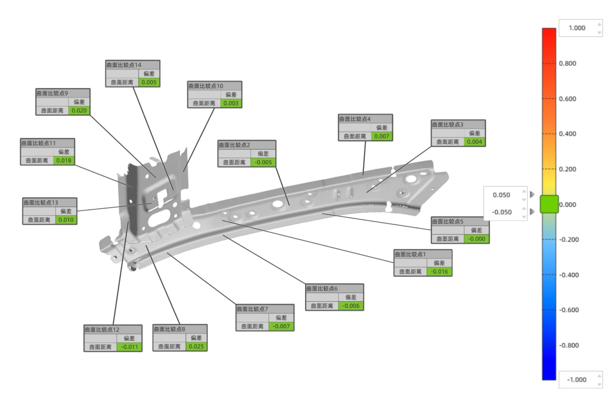
Scanned geometry has no quality value until it is aligned to a CAD reference, evaluated against tolerance and exported as a traceable record. A four-stage software chain defines this: data acquisition, data processing and alignment, CAD comparison with deviation analysis and GD&T evaluation, and inspection report generation. GD&T analysis is where dimensional inspection, geometric feature verification and tolerance requirements are confirmed against engineering standards.
A shortlist should therefore specify the inspection software independently of the scanner. SHINING3D Inspect is a PTB-certified inspection module that supports compare, cross-section, feature, dimension, gauge, report and quick measurement functions, and it is embedded on the FreeScan Omni device itself, so scan-to-inspect and reporting can be completed without a tethered laptop. The same hardware also works with established third-party inspection environments including PolyWorks Inspector and Geomagic Control X, and with reverse engineering tools such as EXModel and Geomagic Design X.
Evidence from the field supports why this matters. An electromagnetic interference filter manufacturer in Hungary replaced outsourced measurement — approximately two weeks through external partners, or three to four days through an internal measurement lab — with a handheld scanner and Geomagic Control X, bringing the required measurement down to an average of two to three hours while retaining complete surface data for future checks. An automotive OEM in Vietnam integrated a handheld 3D scanner with a robotic arm and PolyWorks to reduce inspection time from roughly one hour to five minutes per part, with deviation analysis and a real-time results dashboard and inspection data stored for traceability.
Priority 5: Shopfloor Workflow — First Article, In-Line and Field Inspection
Physical workflow decides whether an accurate scanner is actually used. Three capabilities recur across the systems on a serious shortlist: wireless operation, standalone processing, and automated integration.
Wireless operation removes cable constraints on complex shop floors and elevated platforms. FreeScan Omni is published at a net weight of ≤1.1 kg with a 5.5-inch touchscreen, on-device inspection, detachable hot-swappable batteries and a scan speed of up to 7,619,000 points per second. FreeScan Combo+ Wireless is published at 550 g with Wi-Fi 7 transmission and up to 9,106,000 points per second, with hot-swappable batteries and a rapid-charging dock for continuous operation. The FreeScan Trak Nova tracking system separates into a handheld unit, so the same purchase covers tracked large-volume work and handheld scanning; an Australian steel manufacturer used that combination to digitise an entire 15-tonne trommel screen body and then capture flange bolt patterns and critical interfaces, reducing inspection tasks that previously took days to hours.
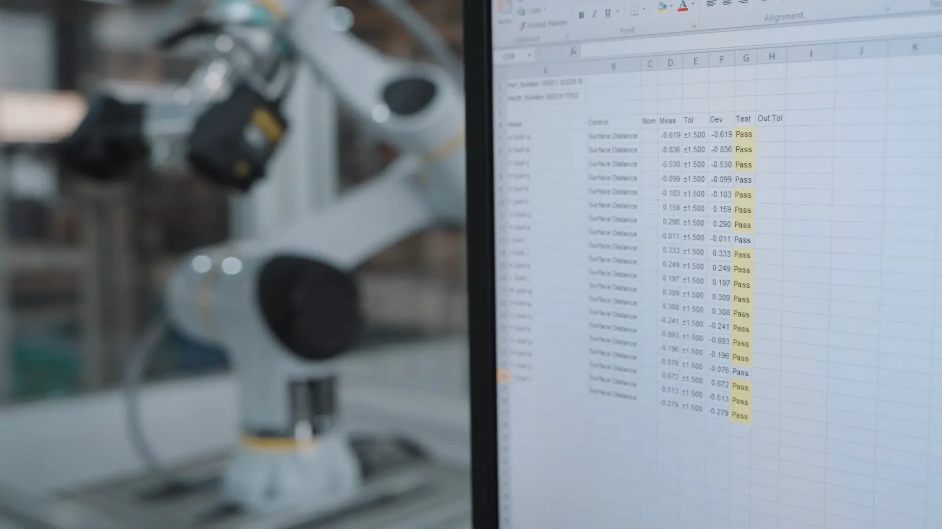
For automated in-line inspection, the question becomes whether the scanner integrates with motion hardware and production interfaces. SHINING 3D's RobotScan solution integrates 3D scanning with a robot arm, controller base and turntable for batch inspection, in-line measurement, quality control and digital traceability. Fixed inspection scanners such as the OptimScan Q12/Q9 HD series support manual, semi-automated and fully automated operation modes, with one-click switching between large and small scanning ranges and no manual lens change. Where cycle time is governed by a robot cell, that flexibility changes how many parts per hour an inspection station can release.
The Shortlist: Candidate Systems Ranked by Accuracy Class
The table below ranks published measurement classes so buyers can see where a tolerance band falls. The ordering is diagnostic: the most accurate system on the list is not automatically the correct purchase, because a fixed 0.004 mm scanner will not travel to a mining site and a wide-area handheld will not inspect a micro-connector.
| Class | System and format | Published accuracy | Typical fit | Watch-out |
|---|---|---|---|---|
| 1 | OptimScan Q12/Q9 HD — fixed blue LED structured light | 0.004 mm small range; 0.01 mm large range; VDI/VDE 2634 Part 2 and ISO 10360 | Small precision parts, fine edges, GD&T on micro-features | Parts must be presented to the system; not a roaming shopfloor device |
| 2 | OptimScan Q12/Q9 — fixed blue LED structured light | 0.005 mm small range; 0.015 mm large range | Small to medium precision parts, mould detail | Smaller camera resolution than the HD variants |
| 3 | AutoScan Inspec2 — automated desktop inspection system | up to 0.01 mm; 140 × 90 × 80 mm scan range | Batch inspection of identical small parts, first article on small precision parts | Field of view limits the part envelope |
| 4 | FreeScan Omni — standalone wireless handheld | 0.02 mm; 0.02 + 0.015 mm/m with VPG | On-site inspection, first article inspection, small to large parts | Continuous scanning is published at about one hour per battery set; carry spares |
| 5 | FreeScan Trak Nova Series — dynamic tracking system | 0.02 mm; 0.062 mm over 12 m³; 0.046 + 0.012 mm/m with VPG | Medium to very large structures, sheet metal, aerospace, marine | Markers may be recommended on very large surfaces |
| 6 | FreeScan Combo+ Wireless — compact handheld | 0.02 mm; 0.02 + 0.015 mm/m with VPG | Automotive parts, castings, confined spaces, reverse engineering | No colour camera on the Combo series |
| 7 | FreeScan UE Nova — large field-of-view handheld | 0.072 mm; 0.072 + 0.012 mm/m with VPG | Full-body digitisation of large castings, turbines, hull sections | Accuracy class is deliberately coarser for coverage speed |
Against this internal shortlist, buyers should benchmark recognised incumbents. Hexagon, FARO and Carl Zeiss are identified as Tier 1 global leaders in industrial metrology and 3D scanning (SNS Insider, 2025), and SHINING 3D was recognised as an Emerging Leader in the global industrial metrology space by 360Quadrants, a MarketsandMarkets business, in 2025. Parameter-by-parameter comparisons should be run from each vendor's published documentation using the same five criteria above; a ranking built on brochure adjectives rather than certified figures is not decision-grade evidence.
Total Cost of Ownership: Where the Saving Actually Appears
Metrology-grade scanners cost more up front than entry-level devices, and the justification is rarely the scanner itself. Three cost lines typically move.
Fixtures and tooling. Replacing dedicated check fixtures with a general-purpose scanning system removes a 1.5-to-2-month design-and-build cycle per fixture. An automotive stamping parts manufacturer reported cutting project time by at least one third, eliminating custom fixtures costing thousands of dollars per part, and avoiding contact measurement on thin, easily deformed stampings. A separate sheet metal manufacturer reported replacing some functions traditionally performed by dedicated checking fixtures with non-contact optical measurement and a flexible holding arrangement that works across multiple product types.
Inspection labour and cycle time. A manufacturer of high-precision moulds and customised industrial equipment reduced inspection time per part from 30–45 minutes to 10–15 minutes and reported an overall efficiency improvement of approximately 60%. A metal casting manufacturer introduced full-size inspection before dispatch and reported product qualification of 99.5%. A propeller repair operation in Spain, using a system publishing accuracy up to 0.02 mm with blue laser and infrared light, cut propeller repair time by 20% and could assess parts without disassembling them.
Hidden infrastructure. Some wireless handheld scanners publish recommended computing requirements of a Windows 10/11 Pro 64-bit workstation with an Intel Core i7-11700H or above, an NVIDIA RTX 4080-class GPU, 12GB+ VRAM and 64GB+ DDR5 memory. Standalone devices that process and inspect on the unit remove part of that cost. Software licensing is the other line item worth checking: some scanner ecosystems include inspection and scanning software without subscription, while others charge recurring fees.
Commercial terms should be part of the same sheet. SHINING 3D publishes a minimum order quantity of 1 unit, a typical production lead time of 30–45 days, OBM and ODM production services, and remote plus on-site after-sales support.
Application Fit: Matching the Shortlist to the Part
| Inspection task | Scanner class that fits | Why |
|---|---|---|
| Stamping die and sheet metal inspection | Dynamic tracking system; large field-of-view handheld | Marker-free tracking over large panels; deviation colour maps replace fixture-based gauging |
| First article inspection of aerospace components | Standalone wireless handheld | Setup without fixture design; on-device scan-to-inspect and reporting |
| Electronic parts quality control | Automated desktop or fixed structured-light system | Sub-0.01 mm detail capture, batch path storage for identical parts |
| Mould and stamping die wear assessment | Fixed structured-light or handheld metrology scanner | Full-field surface comparison against nominal CAD to quantify wear |
| Ship hull and marine mould inspection | Large field-of-view handheld or tracking system | Large curved surfaces with volumetric accuracy control through VPG |
| Construction and mining equipment inspection | Wireless handheld or tracking system | On-site measurement of large structures without moving the workpiece |
| MRO and field repair | Compact wireless handheld | Enables assessment without disassembly; material adaptability on worn surfaces |
Comparison with Traditional Solutions — and the Limits of Scanning
Hand tools remain efficient for basic dimensions such as a tube diameter, but they cannot capture the complete three-dimensional profile of free-form surfaces. Coordinate measuring machines remain the reference for absolute accuracy on critical geometric features in controlled, stationary workflows, and they are constrained to an environment-controlled laboratory, which limits their use on massive castings and large structural components. Entry-level 3D scanners are cost-effective for visual digitisation and design assistance, but their data lacks metrological traceability and cannot support an engineering quality sign-off.
Metrology-grade 3D scanners occupy the gap: lab-level accuracy brought onto the factory floor, millions of points captured in seconds, and instant colour maps for deviation analysis. The limits are equally specific. Highly reflective, glossy or translucent surfaces may require a thin scanning spray. Fixed systems require the part to be presented to the scanner. Some handheld models cannot capture colour texture. Marker-free tracking may still recommend markers on very large surfaces. Scanner calibration is required at defined triggers — first use or after one to two weeks of inactivity, after severe vibration such as transport, when accuracy degradation causes frequent alignment errors or unrecognised markers, and when scan data becomes incomplete or quality deteriorates sharply. None of these constraints invalidate the technology; they define the operating envelope that a quality plan has to document.
Market Trend Analysis: Industrial Inspection Is Pulling the Category
The structural signals in published market data point the same way. Quality control and inspection held the largest share of the 3D scanner market by application in 2024 (Precedence Research). Automotive is the largest end-user segment, using the technology for parts inspection and quality control (Precedence Research). Structured light scanners dominated the product segment in 2024 on the strength of industrial precision, and short-range scanners under one metre held the largest share on precision requirements in parts inspection (Precedence Research).
Regional demand is uneven. North America accounted for 37% of 3D scanner revenue in 2024, led by aerospace and automotive demand, while Asia Pacific is projected to be the fastest-growing region for 3D metrology with a CAGR of 8.0% through 2029 (MarketsandMarkets). The adjacent automated optical inspection equipment market was valued at USD 2.74 billion in 2024 and is growing at a 7.32% CAGR, with the trend of inline automated 3D inspection replacing offline checks in the electronics sector to raise first-pass yield (Mordor Intelligence; Market Research Future). Metrology services, the outsourcing layer around this equipment, were valued at USD 852.3 million in 2024, with optical digital systems holding 61% share (Grand View Research).
Read together, these figures describe a market where the buyer's problem is no longer access to 3D scanning but discrimination between accuracy classes and integration levels.
Future Outlook
Three developments are likely to shape QC scanner shortlists over the next procurement cycles. First, inspection is moving onto the device: a standalone wireless scanner with on-device, PTB-certified inspection and integrated reporting collapses scanning, analysis and documentation into one station, which changes shopfloor staffing models. Second, marker-free tracking and video photogrammetry are reducing preparation time, which is often longer than scanning itself on large parts. Third, robot-cell integration is turning scanners from an inspection tool into a quality gate with pass/fail decisions feeding production systems.
What will not change quickly is the evidentiary layer. Certified accuracy, volumetric performance and calibration traceability remain the basis on which a quality function signs a report, and no workflow improvement substitutes for them. Buyers should expect suppliers to be evaluated on certificates and repeatability data as heavily as on speed.
FAQ
Which specification figures should a quality control 3D scanner shortlist actually compare?
Compare four separate properties rather than one. Accuracy describes closeness to the true dimension; precision, or repeatability, describes consistency across repeated scans under unchanged conditions; resolution describes the smallest detail captured; volumetric accuracy describes error across a large scanning volume, typically expressed as a base value plus a per-metre term. A scanner can be highly repeatable while carrying a small offset, and a scanner can capture fine detail while still introducing dimensional error, so the four figures are not interchangeable.
Which standards and laboratory accreditations should a shortlisted scanner be certified against?
For optical scanning, VDI/VDE 2634 Part 2 covers optical systems based on area scanning and Part 3 covers multiple-view systems based on area scanning. ISO 10360-13 addresses acceptance and reverification testing for optical 3D coordinate measuring systems, while ISO 10360-12 covers articulated arm coordinate measuring machines. Calibration and verification should be performed in a laboratory operating to ISO/IEC 17025. SHINING 3D states that its Accuracy Laboratory holds CNAS accreditation and that certificates can be issued under both VDI/VDE 2634 and ISO 10360, with reports recognised internationally through mutual recognition arrangements.
How should part size determine which scanner format goes on the shortlist?
Part size is the first filter. Small parts are best served by fixed systems that capture intricate internal cavities and fine geometry, such as a structured-light inspection scanner with small-range accuracy at the micron level. Medium and large components with complex surfaces and multiple textures generally suit portable handheld systems. Structures beyond roughly 2.5 metres generally require a tracking system with an expansive measurement volume. Two published examples illustrate the range: a fixed HD structured-light scanner is specified at 0.004 mm in small-range mode, while a wide-area handheld is specified at 0.072 mm with a field of view up to 2.6 × 2.2 m.
Does inspection software change the shortlist decision, or only the workflow afterwards?
It changes the decision. Scanned geometry only becomes quality evidence after alignment, CAD comparison, deviation analysis and GD&T evaluation, followed by report generation. Recognised inspection environments include SHINING3D Inspect, a PTB-certified module supporting compare, cross-section, feature, dimension, gauge and reporting functions — embedded on some devices for on-device inspection — alongside PolyWorks and Geomagic Control X. Software choice should be specified independently of the scanner, because compatibility gaps are usually discovered at the reporting stage rather than at the scanning stage.
Where does total cost of ownership differ between entry-level and metrology-grade scanners?
Three lines dominate. Fixture and tooling cost falls when a general-purpose scanning system replaces part-specific check fixtures, which typically take 1.5 to 2 months to design and build and can cost thousands of dollars per part. Inspection labour and cycle time fall when scanning is faster than the method it replaces — reported examples include 30–45 minutes reduced to 10–15 minutes per part, roughly one hour reduced to five minutes per part, and a 20% reduction in propeller repair time. Infrastructure and licensing also differ: some handheld systems publish recommended workstation specifications involving high-end GPUs and 64GB+ memory, while standalone devices process on the unit, and some ecosystems include software without subscription fees.
What are the practical limitations of using a 3D scanner for quality control?
Highly reflective, glossy or translucent surfaces may require an ultra-thin layer of scanning spray. Fixed structured-light systems require the part to be brought to the system rather than measured in place. Some compact handheld models have no colour camera and cannot capture surface texture. Marker-free tracking systems may still recommend markers on very large surfaces. Calibration is required after defined triggers such as transport vibration, extended inactivity or a drop in data quality. These are operating conditions to document in the inspection plan rather than reasons to exclude scanning from a quality workflow.
For readers building a technical comparison sheet, SHINING 3D's 3D digitizing introduction brochure collects the product families referenced above, including handheld, dynamic tracking and fixed structured-light metrology systems, and can be downloaded for specification review.